Shenzhen Hpmont Technology Co., Ltd Appendix C Communication Protocol
HD30 Series Inverters User Manual -165-
The users can realize the inverter’s starting, stopping and running speed setting through the
control parameter, and obtain the inverter’s running frequency, output current, etc. through
indexing the inverter’s status parameters.
1. Control parameters
The inverter’s control parameter intergroup indexes are as follows:
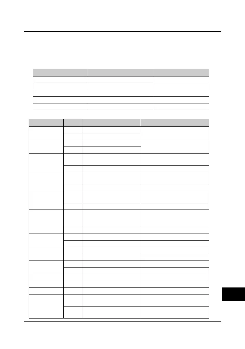
Register address Parameter name Retained or not at power loss
0x3200 Control command character No
0x3201 Running frequency setting No
0x3202 Auxiliary running frequency setting No
0x3203 Reserved
0x3204 Virtual terminal control setting No
Definition of inverter control command words:
Control word (Bit) Value Definition Function description
Bit0
1 Run command enabled
To control the inverter’s starting and
stop (in edge triggering mode)
0 Run command disabled
Bit1
0 Forward
Running direction: have the same
function as terminal FWD/ REV
1 Reverse
Bit2
1 Stop mode: Decelerate to stop
Decelerate to stop the inverter (in
edge triggering mode)
0 Reserved
Bit3
1 Stop mode: emergency to stop
Emergency to stop the inverter (in
edge triggering mode)
0 Reserved
Bit4
1 Stop mode: coast to stop
Coast to stop the inverter (in edge
triggering mode)
0 Reserved
Bit5
1 Stop mode: external fault
External fault stop control, the inverter
will coast to stop, displaying external
fault
0 Reserved
Bit6
1 Jog forward run Jog forward control
0 Jog forward stop
Bit7
1 Jog reverse run Jog reverse control
0 Jog reverse stop
Bit8
1 Fault reset enabled Fault reset control
0 Fault reset disabled
Bit9 0 Reserved
Bit10 0 Reserved
Bit11 0 Reserved
Bit12
1 Current control enabled
The current sending control word is
valid
0 Current control disabled
The current sending control word is
valid
C

 Loading...


