Chapter 3 Mechanical Installation Shenzhen Hpmont Technology Co., Ltd
―12― HD30 Series Inverters User Manual
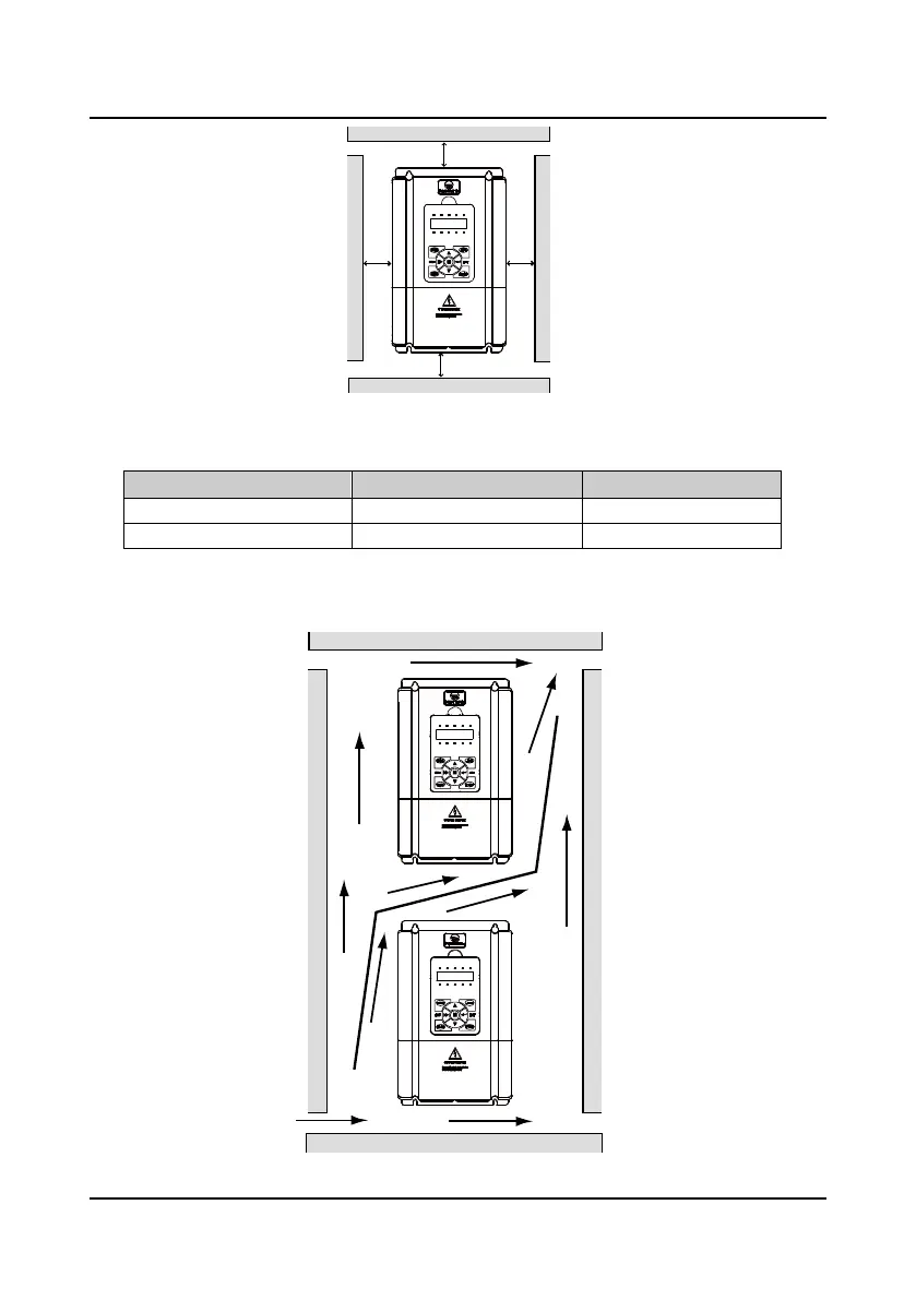
Figure 3-1 Installation of the inverter
Table 3-1 Installation dimension of the inverters
Inverter power A(left and right) B(up and down)
55kW or below 50mm above 100mm above
75kW or above 150mm above 350mm above
When one inverter is mounted on the top of the other, an air flow diverting plate should be fixed in
between. Just as shown in Figure 3-2.
Figure 3-2 Installation of several inverters
LOCK
FWD REV ALM
LO/RE
HZ A V RPM
%
A
B
A
B
LOCK
FWD REV ALM
LO/RE
A V RPM
%
LOCK
FWD REV ALM
LO/RE
A V RPM
%
HZ
HZ
 Loading...


