Shenzhen Hpmont Technology Co., Ltd Chapter 4 Electrical Installation
HD30 Series Inverters User Manual ―33―
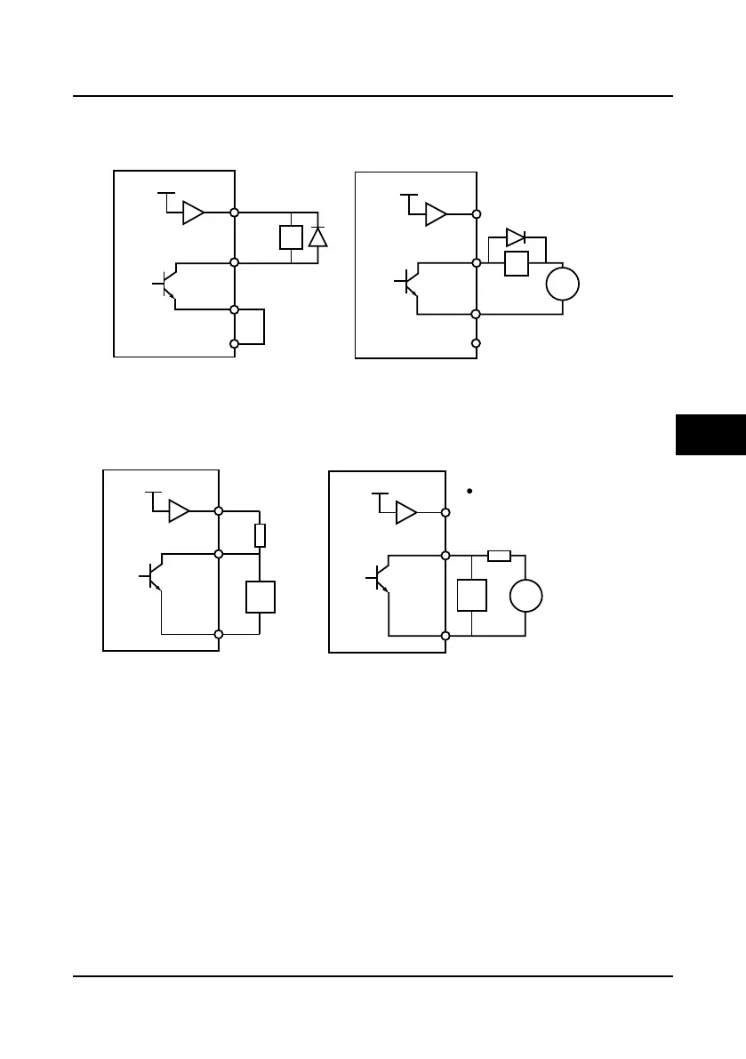
Wiring of multi-function output terminal
1
.
The multi-function output terminal DO1 can use the inverter’s internal 24V power supply or the
external power supply. The connections are as shown in Figure 4-22.
Figure 4-22 DO1 terminal connection
2
.
The frequency signal output terminal DO2 can use the inverter’s internal 24V power supply or
the external power supply. The connections are as shown in Figure 4-23.
Figure 4-23 DO2 terminal connection
DO1
+ 24V
P24
DO1
+ 24V
P24
Using the internal 24V power supply
CME
CME
12-30V
DC
COM
COM
+
-
Relay
coil
Relay
coil
Using the external power supply
DO2
COM
+ 24V
R
P24
DO2
COM
+ 24V
R
P24
R: 10KΩ resistor
f
f: digital frequency counter
f
12-30V
DC
+
-
Using the internal 24V power supply Using the external power supply
4

 Loading...


