Chapter 5 Operation Instructions Shenzhen Hpmont Technology Co., Ltd
―42― HD30 Series Inverters User Manual
Table 5-4 Switching four-level description of the key
Key First-level menu Second-level menu Third-level menu Fourth-level menu
Fault, return to faulty
display; Fault
cleared, return to
run/stop status
display.
Return to first-level
menu
Return to
second-level menu
Do not save the current value
and return to third-level
Enter to second-level
menu
Enter to third-level
menu
Enter to fourth-level
menu
Save the current value and
return to third-level
Select function
group.
Cycle according to
d-F-P-U-y
Modify No. function.
Increase by 1 when
press this key one
time
Modify the internal
No. of function group.
Increase by 1
according to the
current modified bit
Modify function value.
Increase by 1 according to
the current modified bit
Select function
group.
Cycle according to
y-U-P-F-d
Modify No. function.
Decrease by 1
when press this key
one time
Modify the internal
No. of function group.
Decrease by 1
according to the
current modified bit
Modify function value.
Decrease by 1 according to
the current modified bit
Invalid Invalid Switch units and tens
Switch units, tens, hundreds,
thousands , ten thousands
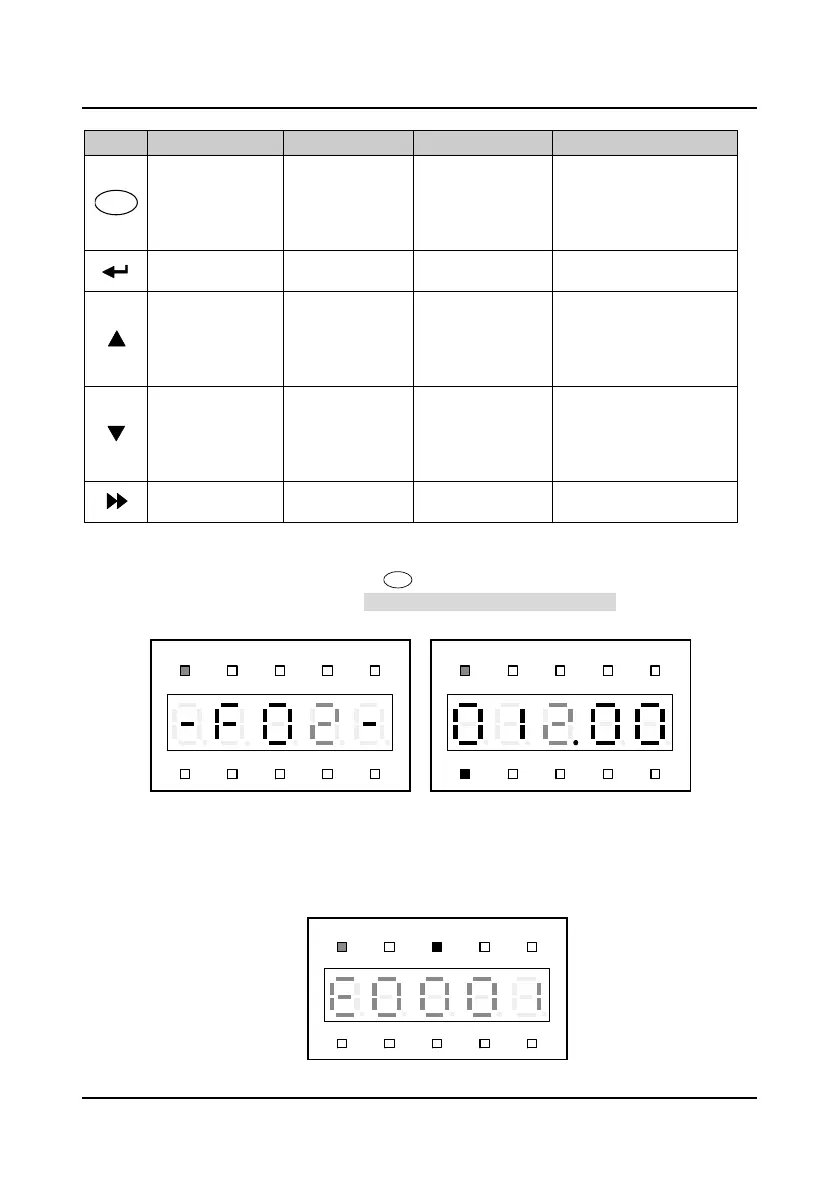
Function parameter editing status
At stop, run or fault alarm status, press to enter function parameter editing status (see the
description of parameter F01.00 and the user password unlock and modify of section 5.2.3), as
shown in Figure 5-5.
Figure 5-5 Parameter editing status
Fault alarm status
If the inverter detects a fault signal, the display panel will enter the fault alarm status and flashing
display the fault code, as shown in Figure 5-6.
You can enter Group F20 (F20.21
-
F20.37) to check the fault history.
Figure 5-6 Fault alarm status
Hz
A V RPM %
REVFWD ALM LO/RE LOCK
Hz
A V RPM %
REVFWD ALM LO/RE LOCK
Hz
A V RPM %
REVFWD ALM LO/RE LOCK
 Loading...


