Shenzhen Hpmont Technology Co., Ltd Chapter 5 Operation Instructions
HD30 Series Inverters User Manual ―45―
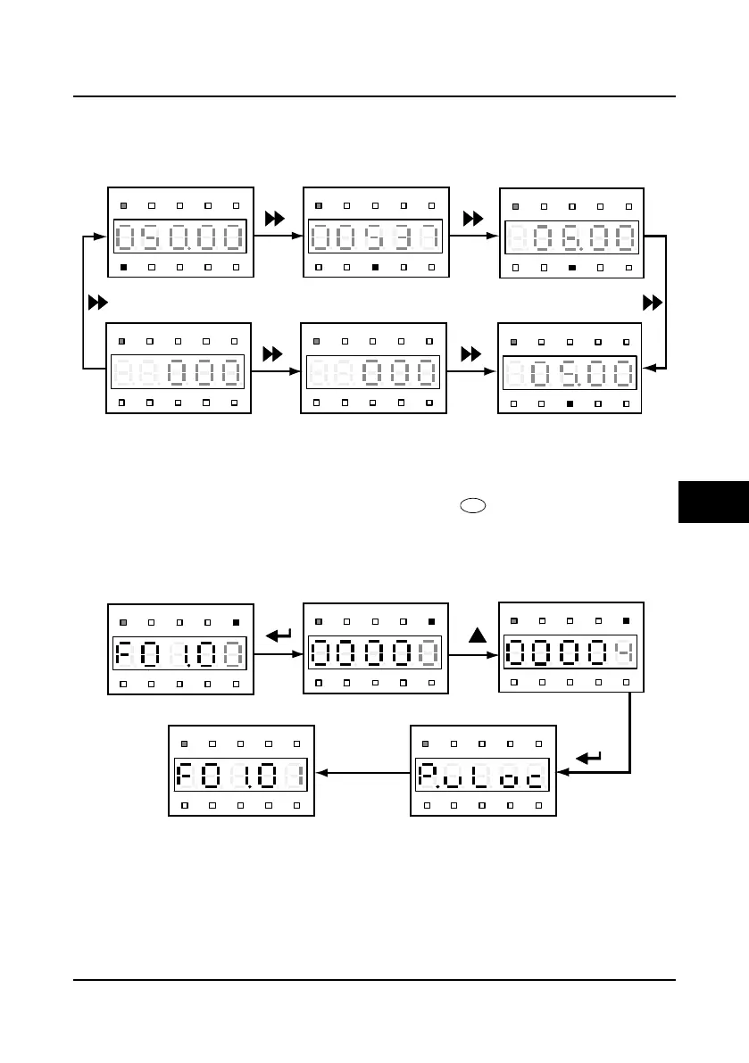
Switching display parameters at stop status
There are six stop parameters(F18.08
-
F18.13) of the HD30 inverter. For example, set the
parameter to be default value and the Figure 5-9 describes the operation of displaying
parameters.
Figure 5-9 Switching display parameters at stop status
Unlock user’s password
When user set F01.00 to non-zero value, by pressing the key to exit to stop/run display
status or by detecting that there is no press on the display panel within 5 minutes, the user’s
password will be valid. The status indicator of the display panel is lighting at the moment.
The operation of the unlock user’s password is as shown in Figure 5-10 which takes 4 as the
user’s password.
Figure 5-10 Operation of unlocking user’s password
Hz
A V RPM %
REVFWD ALM LO/RE LOCK
Setting frequency
F18.08 = 7
Hz
A V RPM %
REVFWD ALM LO/RE LOCK
DCbus voltage
F18.09 = 18
Hz
A V RPM %
REVFWD ALM LO/RE LOCK
AI1input voltage
F18.10 = 20
Hz
A V RPM %
REVFWD ALM LO/RE LOCK
F18.13 = 44
Hz
A V RPM %
REVFWD ALM LO/RE LOCK
Input terminal status
F18.12 = 43
Hz
A V RPM %
REVFWD ALM LO/RE LOCK
AI2input voltage
F18.11 = 22
Output terminal status
Hz
A V RPM %
REVFWD ALM LO/RE LOCK
Hz
A V RPM %
REVFWD ALM LO/RE LOCK
Hz
A V RPM %
REVFWD ALM LO/RE LOCK
Hz
A V RPM %
REVFWD ALM LO/RE LOCK
Hz
A V RPM %
REVFWD ALM LO/RE LOCK
1.5seconds later
Third-level menu
Third-level menu Fourth-level menu Input correct password
Unlock passwordsuccess
5
 Loading...


