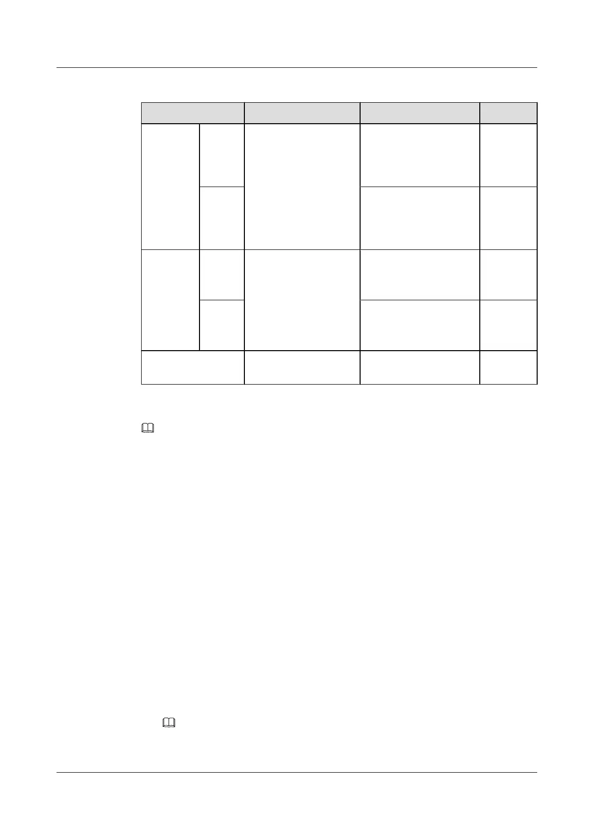
Table 6-10 Specifications of RRU power cables
Cable One End The Other End Remarks
RRU
power
cable
RTN(+)
wire
Easy power receptacle
(pressfit type) connector
OT terminal [M4, 3.3
mm
2
(12 AWG)]
North
American
standard
Black
NEG(-)
wire
OT terminal [M4, 3.3
mm
2
(12 AWG)]
North
American
standard
Blue
RRU
power
cable
RTN(+)
wire
Easy power receptacle
(pressfit type) connector
OT terminal (M4, 4 mm
2
)
European
standard
Brown
NEG(-)
wire
OT terminal (M4, 4 mm
2
)
European
standard
Blue
RRU power cable Easy power receptacle
(pressfit type) connector
Easy power receptacle
(pressfit type) connector
NOTE
The colors and structures of cables vary according to countries and areas. If the cables are purchased locally,
the colors and structures of the cables may be different.
Procedure
Step 1 Prepare an RRU power cable.
1. Cut the cable to the required length based on the actual cable route.
2. Add an easy power receptacle (pressfit type) connector to one end of the RRU power cable.
For details, see Assembling the Easy Power Receptacle (Pressfit Type) Connector and the
Power Cable.
3. Add OT terminals or an easy power receptacle (pressfit type) connector to the other end of
the RRU power cable according to the type of power supply socket on the RRU.
l Add an OT terminal. For details, see the related RRU Installation Guide.
l Add an easy power receptacle (pressfit type) connector. For details, see the related RRU
Installation Guide.
Step 2 Install an RRU power cable, as shown in Figure 6-80.
1. Link the easy power receptacle (pressfit type) connector at one end of the RRU power cable
to the RRU0 port on the EPS subrack.
NOTE
An EPS subrack supplies power to a maximum of six RRUs. Therefore, an RRU power cable can be
connected to any of the RRU0 to RRU5 ports on the EPS subrack.
DBS3900 (Ver.B)
Installation Guide
6 Outdoor Scenario with AC Power Supply (BBU Installed
in an APM30H)
Issue 06 (2011-09-15) Huawei Proprietary and Confidential
Copyright © Huawei Technologies Co., Ltd.
89