l If a new base station supports not more than eight E1s, route the ends of the E1/T1 cables
connected to the SLPU along the right of the cabinet.
l If a new base station supports more than eight E1s, route the ends of other E1/T1 cables
connected to the SLPU along the left of the cabinet.
NOTE
The descriptions about the installation positions and routes of the E1/T1 cables in the -48 V DC cabinet
and in the APM30H are the same. For details, see Figure 6-83 or Figure 6-84.
Procedure
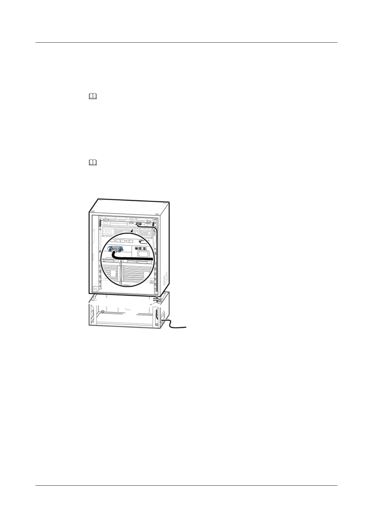
Step 1 Connect one end of the E1/T1 cable to the OUTSIDE port on the UELP, as shown in Figure
6-83 or Figure 6-84.
NOTE
For details about how to connect the E1/T1 cable, see Transmission Cable Connections.
Figure 6-83 Installing the E1/T1 cable (1)
DBS3900 (Ver.B)
Installation Guide
6 Outdoor Scenario with AC Power Supply (BBU Installed
in an APM30H)
Issue 06 (2011-09-15) Huawei Proprietary and Confidential
Copyright © Huawei Technologies Co., Ltd.
93