Figure 6-85 Installing a FE/GE surge protection transfer cable
Step 2 Route the cables by referring to 6.5.1 Cabling Requirements, and then use cable ties to bind
the cables.
Step 3 Label the installed cables by referring to Attaching an L-Shaped Label.
----End
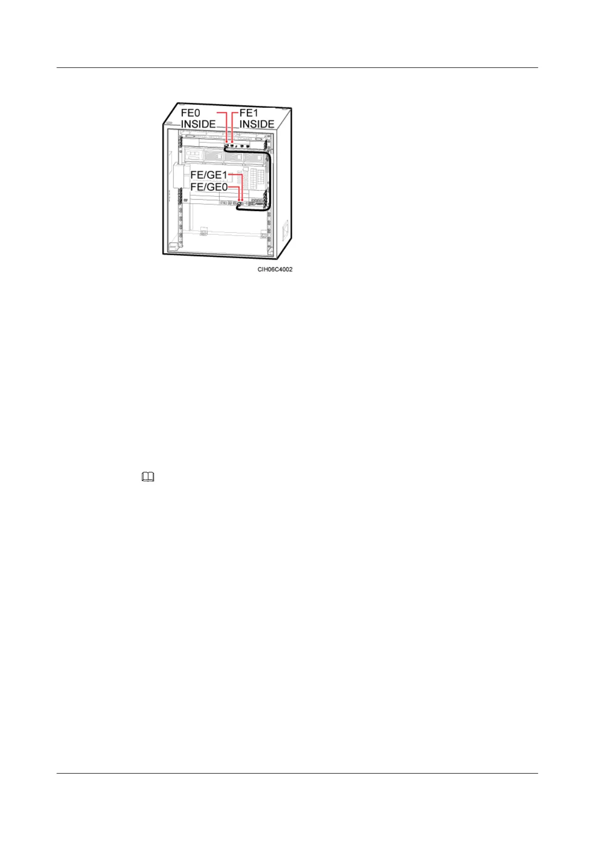
Installing the FE/GE Cable
This section describes the procedure and precautions to be taken for installing an FE/GE cable.
Procedure
Step 1 Connect one end of the FE/GE cable to the FE0 or FE1 port near the OUTSIDE label on the
UFLP, as shown in Figure 6-86 or Figure 6-87.
NOTE
l You must use shielded straight-through FE/GE cable.
l For details about how to connect the FE/GE cable, see Transmission Cable Connections.
l The descriptions about the installation positions and routes of the FE/GE cables in the -48 V DC cabinet
and in the APM30H are the same. For details, see Figure 6-86.
DBS3900 (Ver.B)
Installation Guide
6 Outdoor Scenario with AC Power Supply (BBU Installed
in an APM30H)
Issue 06 (2011-09-15) Huawei Proprietary and Confidential
Copyright © Huawei Technologies Co., Ltd.
95