Prerequisite
WARNING
Before soldering the connectors to the E1/T1 cable, ensure that both ends of the E1 cable are
disconnected from any devices. In addition, all the connectors are soldered to the E1 cable during
the same session.
Procedure
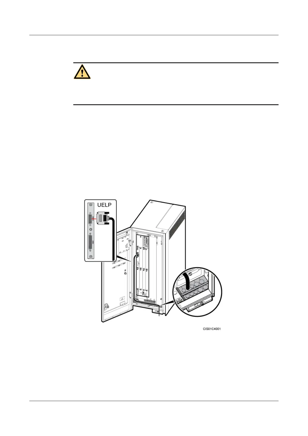
Step 1 Install an E1/T1 cable, as shown in Figure 9-25.
1. Link the DB26 connector at one end of the E1/T1 cable to the OUTSIDE port on the UELP
in the BBU, and then tighten the plastic screws on the connector until the tightening torque
reaches 0.25 N·m.
2. Lead the other end out of the cabinet through the cable outlet module on the bottom right
of the cabinet, and then connect the E1/T1 cable to the external transmission equipment.
For details about how to install the cable outlet module, see 9.4.2 Installing a Cable Outlet
Module in an OMB.
Figure 9-25 Installing an E1/T1 cable
Step 2 In a position 20 cm away from the cable outlet module, strip the jacket for about 25 mm off the
E1/T1 cable to expose the shielding layer. Thread the E1/T1 cable through the ground clip to
ensure full contact between the shielding layer and the ground clip, and then tighten the M4
screws on the clip until the tightening torque reaches 1.2 N·m, as shown in Figure 9-26.
DBS3900 (Ver.B)
Installation Guide
9 Outdoor Scenario with DC Power Supply (BBU Installed
in an OMB)
Issue 06 (2011-09-15) Huawei Proprietary and Confidential
Copyright © Huawei Technologies Co., Ltd.
312
 Loading...


