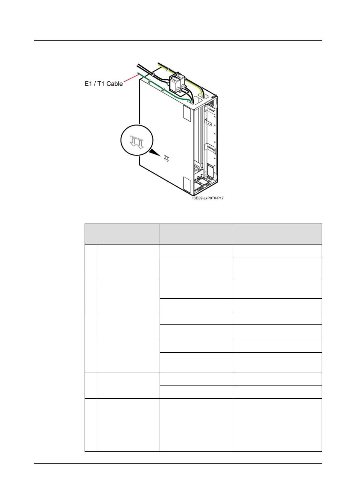
Figure 13-56 Routes of the E1/T1 cable and GPS clock signal cable
Table 13-5 Cable list
S
N
Cable Connector Installation Position
a PGND cable for the
IMB03
OT terminal (16 mm
2
, M6)
Ground terminal in the IMB03
Connector added on site The nearest wiring terminal on
the ground bar
b PGND cable for the
GPS surge protector
OT terminal (6 mm
2
, M8)
Ground terminal on the GPS
surge protector
OT terminal (6 mm
2
, M4)
Ground terminal in the IMB03
c BBU power cable (in
the DC power supply
scenario)
3V3 power connector Power supply port on the UPEU
OT terminal (1.5 mm
2
, M4)
LOAD6 port on the DCDU-03B
BBU power cable (in
the AC power supply
scenario)
3V3 power connector Power supply port on the UPEU
H4 connector LOAD1 port on the AC/DC
power device
d E1/T1 cable DB26 connector E1/T1 port on the GTMU
Connector added on site External transmission equipment
e Input power cable (in
the DC power supply
scenario)
OT terminal (16 mm
2
, M6)
Wiring terminal labeled NEG for
the blue wire of the input power
cable on the DCDU-03B
Wiring terminal labeled RTN for
the black wire of the input power
cable on the DCDU-03B
DBS3900 (Ver.B)
Installation Guide 13 Indoor Scenario (BBU Installed in an IMB03)
Issue 06 (2011-09-15) Huawei Proprietary and Confidential
Copyright © Huawei Technologies Co., Ltd.
489