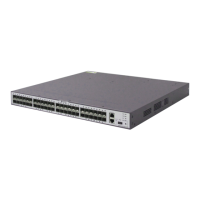
Figure 10-1 Console cable connection
1 2 3 4 5 6 7 8 9 10 11 12 13 14 15 16 17 18 19 20 21 22 23 24 25 26 27 28 29 30 31 32 33 34 35 36 37 38 39 40 41 42 43 44 45 46 47 48
MODE
STCK
SPED
STAT
SYS
PWR2
PWR1
PoE
HUAWEI
S5710-52C-PWR-EI
1234
CONSOLE
ETH
RJ-45
DB-9
NOTE
l After connecting both ends of the console cable, power on the switch. During the startup sequence of
the switch, you can choose whether to enter the BootROM menu. The BootROM menu and the
procedure to enter it vary depending on software versions. For details, see the upgrade guide for the
switch and software version in use.
l If a switch has a mini USB port, you can also use a mini USB cable to connect the switch to a
maintenance terminal.
Step 4 Turn on the external power supply system connected to the switch.
Step 5 Turn on the power switch on the switch or power module.
NOTE
Skip this step if the switch does not support pluggable power modules or does not have a power switch.
Step 6 After the switch completes its startup sequence, check the indicators on the switch and power
modules.
The SYS indicator on the switch and the STATUS indicators on the fan modules and power
modules should be steady green. For details about indicator states and meanings, see 13.1
Appendix A Indicators.
NOTE
After startup, the command line interface (CLI) is displayed, through which you can configure the
switch. For details about how to configure the switch and the configuration commands used, see the
CLI-based Configuration Guide for the switch.
----End
Follow-up Procedure
To power off the switch, perform the following steps:
NOTICE
Powering off the switch will interrupt all services on the switch. Exercise caution when you
perform this operation.
S2700&S3700&S5700&S6700 Switch
Hardware Installation and Maintenance Guide
10 Powering on a Switch for the First Time
Issue 13 (2017-11-20) Huawei Proprietary and Confidential
Copyright © Huawei Technologies Co., Ltd.
75
 Loading...