Indicato
r
Name Color Status Meaning
Orange Blinking (on for 0.25
s and off for 0.25 s
repeatedly)
A high-temperature alarm
is generated
Red On The board is faulty
MAJ Alarm
indicators
Red On The system has generated a
major alarm
MIN Alarm
indicators
Red On The system has generated a
minor alarm
IN0,IN1 IN0
indicator,
IN1
indicator
Green On The signals are correct
- Off There are no signals or the
signals are incorrect
ETH ETH
indicator
Green On The port has a connection
set up
Green Blinking Data is being transmitted
- Off The port has no connection
or no data is being
transmitted over the link
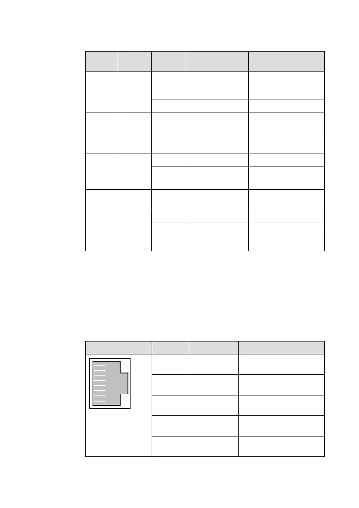
Pin Assignment
Table 3-158, Table 3-159, Table 3-160, Table 3-161, Table 3-162, Table 3-163 and Table
3-164 show the pin assignments of the BITS/TOD IN0 port, BITS/TOD IN1 port, BITS/TOD
OUT port, ETH port, COM port, ALM port (upper) and ALM port (lower) on the front panel
of the H806VPEF board.
Table 3-158 Pin assignments of the BITS/TOD IN0 port
Port
Pin Signal Remarks
1 BITS0_IN_B Input B of channel 0 BITS
clock signals
2 BITS0_IN_A Input A of channel 0 BITS
clock signals
3 PPS0_IN- Negative polarity of channel 0
PPS time signals
4 TOD0_IN- Negative polarity of channel 0
TOD time signals
5 TOD0_IN+ Positive polarity of channel 0
TOD time signals
SmartAX MA5600T/MA5603T/MA5608T Multi-service
Access Module
Hardware Description
3 Board
Issue 24 (2018-07-30) Huawei Proprietary and Confidential
Copyright © Huawei Technologies Co., Ltd.
737

 Loading...