English - 12
The Automower® cannot enter the charging
station when there is no N signal. The
mower will eventually stop and display the
Low battery fault message.
• Guide signal
The signal that the charging station transmits
through the guide wires. The guide signals
lead the mower to the charging station, but
can also be used to direct the mower to a
remote area. Guide 1, Guide 2 and Guide 3
are marked on the connections on the back
of the charging station.
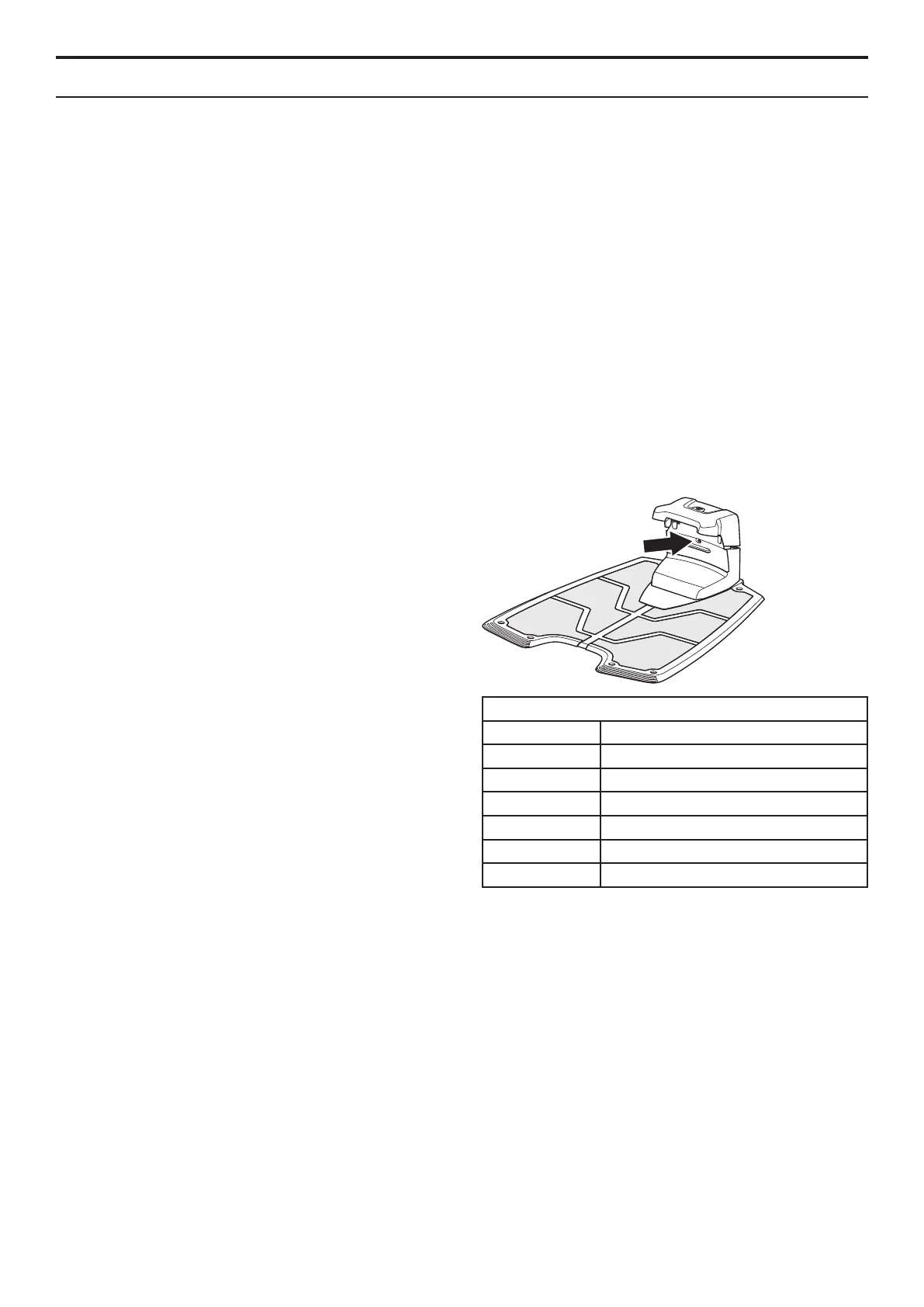
1.7 Loop system status
The loop system status is most easily checked using
the LED in the charging station. Check the loop sig-
nals by checking what the LED is indicating.
• Solid green light = All signals are good.
• Green ashing light = The A signal has been
turned off in the boundary wire (ECO mode).
• Blue ashing light = No signal in the
boundary wire (A signal). Most likely a break
in the boundary wire.
• Red ashing light = No F signal. Most likely
interruption in the charging station’s antenna
plate.
• Solid blue light = Weak signal in the
boundary wire (A signal). This may depend
on the boundary wire being over 800 m in
length or that the wire is damaged. If the
mower still works, this is not a problem.
• Solid red light = fault in the circuit board in
the charging station.
Suggested action in case of fault indication, refer to
6.4 Troubleshooting the loop signal.
1.8 Boundary wire
The strength of the signal in the boundary wire is
constant in a loop that is up to approx. 800 meters
in length. If, however, the loop is longer than
800 meters, the strength can start to diminish, even
though it is still sufcient.
Table 1: Colors in the charging station's LED
Color Status
Solid green light
All signals are OK
Green ash ECO mode
Blue ash Break in the boundary wire
Red ash Break in the F or N loops
Solid blue light Poor signal from boundary wire
Solid red light Faulty circuit board
1. FUNCTION

 Loading...