English - 77
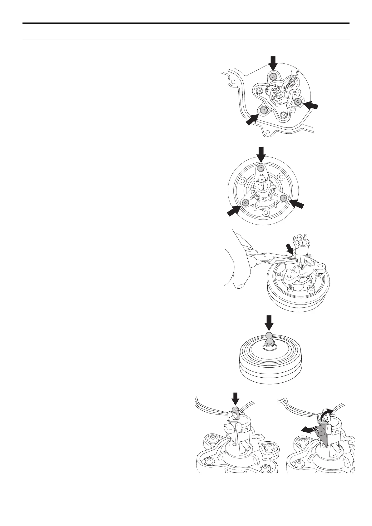
3. Unscrew the 3 screws (Torx 20) securing the
front collision brackets to the chassis.
4. Loosen the 3 screws securing the bracket to
the collision column.
5. Depending on which part of the collision
column bracket is to be replaced, a varying
amount of disassembly is required.
By pulling out the split pin using pliers, the
collision column can be split to give access
to the spring.
To replace the rubber diaphragm or the
inner column, the snap-on fastener must be
unscrewed.
To replace the sleeve for the lift sensor, the
lift sensor circuit board must also be removed
by bending the snap-on fastener. The cable
tie must also be removed. NB! Use a new
cable tie when tting the new sleeve.
6. Ret all components, the chassis and body.
5. REPAIR INSTRUCTIONS

 Loading...