3 Installation and Dimension
3 - 7
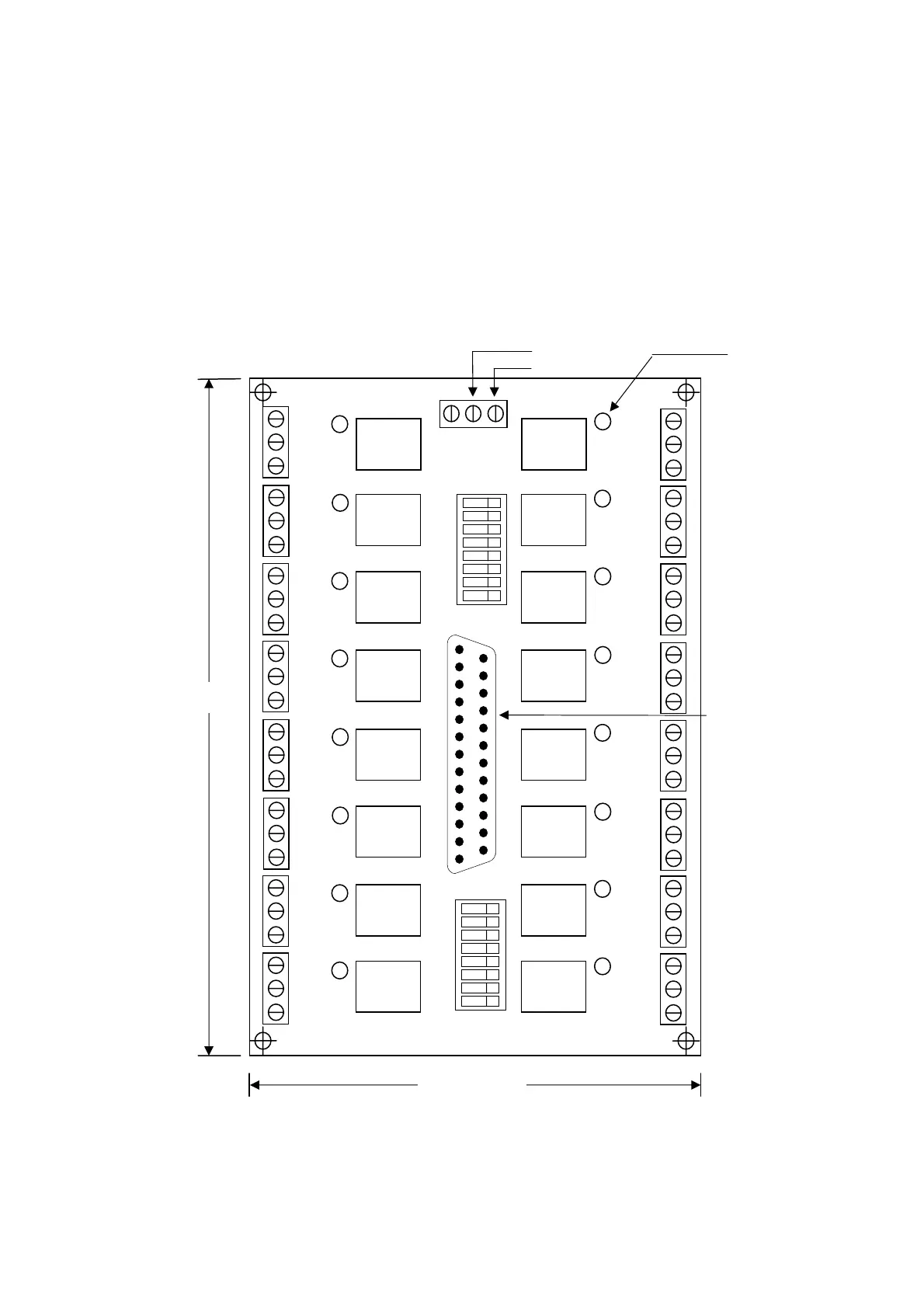
• Output Relay Board – NPN Type
Fig 3-7 is a NPN type output relay board and it has 16 outputs with LED indicators.
When the output signal is properly received, the corresponding LED will be ON.
Normally, all DIP switches are at "OFF" position. In this case, all connections on
COM and NO will be done in normal manner. If the DIP switch is at “ON” position,
COM becomes the ground (GND) of 24V. If you have an external device, such as
relay valve or DC motor, that is driven by 24V ground, just push the corresponding
DIP switch to “ON” and no 24V grounding connected to COM is necessary.
NO = Normal Open, COM = Common
Fig 3-7 Output Relay Board
LED
Indicator
RELAY
NPNO_2S\N:
O07
O06
O05
O04
O03
O02
O01
O00
DIP Switch
+24V
GND
+24V
DB25LM
Connector
155 mm
107 mm
+24V
COM7
NO0
7
+24V
COM6
NO06
+24V
COM5
NO05
+24V
COM4
NO04
+24V
COM3
NO03
+24V
COM2
NO02
+24V
COM1
NO01
+24V
COM1
NO01
24V Power
RELAY
+24V
COM15
NO015
+24V
COM14
NO014
+24V
COM13
NO013
+24V
COM12
NO012
+24V
COM11
NO011
+24V
COM10
NO010
+24V
COM09
NO009
+24V
COM09
NO009
O15
O14
O13
O12
O11
O10
O09
O08