4 Connecting Diagrams
4 - 3
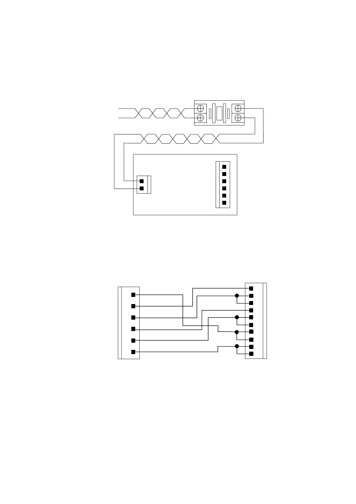
z AC Power Supply Connecting Diagram (Fig 4-2)
HUST H2N controller requires an AC110~220V± 10% power. Try to avoid
excessive power fluctuation or it will not work properly. All components in Fig
4-2 are inside the control box and it's shown here for reference only.
Fig 4-2 AC Power Supply Connection
z DC Power Supply Connecting Diagram (Fig 4-3)
The DC power connections have been done in the factory. In the case that it
becomes necessary to reconnect yourself, please use Fig 4-3 for reference.
Fig 4-3 DC Power Supply
1
2
3
4
5
6
+12V
+5V
+5V
0V
0V
-12V
AC TO DC Power Supply
DC out
AC In
AC Power Filler
R
T
AC 220V
1
2
3
4
5
6
+12V
+5V
+5V
0V
0V
-12V
DC Output Connector
(AC TO DC Power Supply, Fig 4-2)
P1 Connector on Main Board
(DC Power)
1
2
3
4
5
6
7
8
9
10
+5V
+5V
+5V
0V
0V
0V
+12V
+12V
-12V
-12V