4 Connecting Diagrams
4 - 5
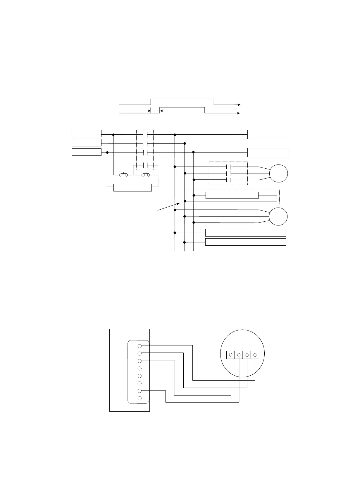
z AC Power System Connection (Fig 4-5)
HUST internal PLC in the controller has a timer to control the servo-on delay.
When the set time (about 1.5 seconds) in this timer has elapsed, an output is ON
to turn on the servo motors.
Fig 4-5 AC Power Connection to Servo Driver
z MPG Hand-wheel Connecting Diagram (Fig 4-6)
If the tool movement is in the opposite direction to the MPG hand-wheel rotation,
please exchange A and B signal connections.
Fig 4-6 MPG Hand-wheel connection
CNC Power-on
Time
CNC Power-on
Time
servo on delay
R
TS
To CPU Power supply R
To CPU Power supply T
AC220V R
AC220V S
AC220V T
Servo
Driver
Timer Delay Contac
Fan
power-off
power-on
Power-On Relay
Powe
-On Timer Rela
AC 220V R T0 Servo AMP Power TB P
AC 220V S T0 Servo AMP Power TB N
Can be omitted inside dashed line
CPU Main Board
P3
0V
0V
MPG
+5V 0V A B
1
2
3
4
5
6
7
8