HUST H2N Connecting Manual
8 - 2
8. On "Load Disk Data File" screen, select your "*.evn" system (PLC ladder) file
with the appropriate directory path. Press ENTER.
9. Start address – 00000 for system file, 0C000 for PLC. Press ENTER. Fill -- N.
Once "N" has been entered, the "*.evn" file selected in Step 6 will be loaded into
the PC memory. Press ENTER to return to the main menu.
10. Repeat Steps 5~9 for PLC file with the starting address = 0C000 for PLC.
11. On the main screen, select "Parameter". Make sure Vcc = 5.0V, Vpp = 5.0V.
12. Insert a blank EPROM into the writer.
13. Press "P" or select "Program" to start writing "*.evn" file into the FLASH-ROM.
14. Remove the EPROM from the writer and mark EVN.
15. Repeat Steps 5~9 and 10~13 for writing "*.odd" file. Mark ODD on the
EPROM.
16. Press "Ctrl Esc" to quit.
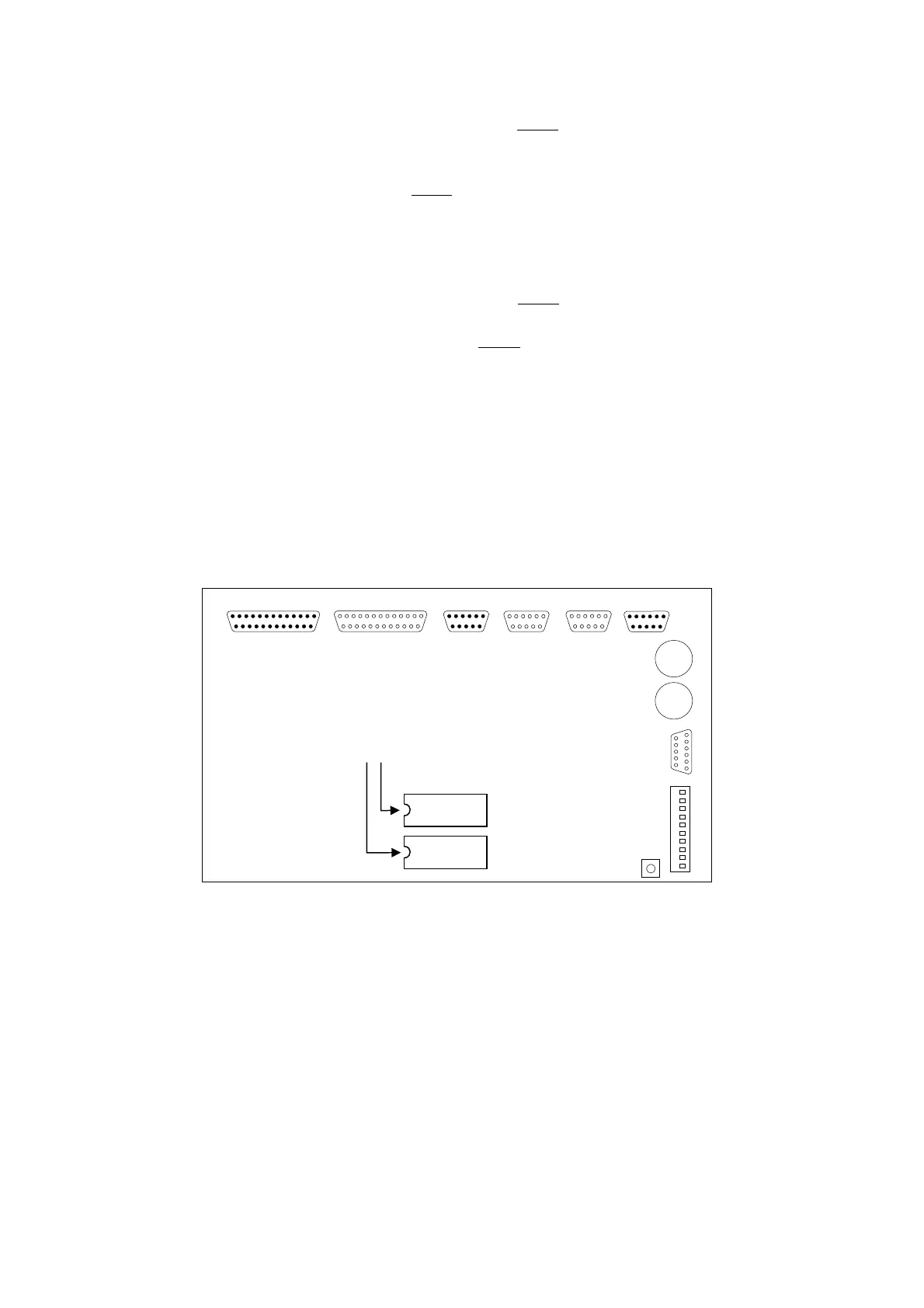
8.3 EPROM Installation
The 68000 CPU board in HUST H2N controller has two slots for even and odd
system and PLC ladder EPROMs. The slot designation for even system and PLC
ladder EPROM is EVN and for odd system and PLC ladder EPROM is ODD. Be
careful about the locations when installing those EPROMs. They must be correctly
installed in the appropriate slot (see Fig 8-1) or the controller will not work properly .
Fig 8-1 Installation of FLASH-ROM
OUTPU
P1 (Male)
INPU
P2 (female)
MPG
P3 (M)
P4 (F)
Y
P5 (F)
D
A
P6 (M)
RS232
P7 (F)
JP1
DC
BT1
BT2
ontra
R7
ODD
EVN
※ Pay attention to the notch
direction on FLASH-ROM