HUST H2N Connecting Manual
9 - 4
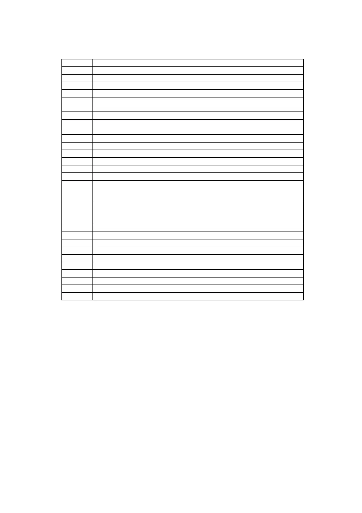
Table A2 Meaning of Command Format Representation
Item No Meaning of Command Representation
1 Stop report
2 RESET control
3 AUTO mode
4 SINGLE mode
5 MDI mode. Input MDI data to controller. The MDI data is typed in the next line as
"Gxx X-123.45 Y123.45 F123.45 .....<CR>
6 CYCLE START
7 Current program position during execution
8 Current machine position
9 Tool feedrate
10 Spindle speed
11 Current tool offset
12 Current block counter
13 The controller reads program from PC. Item No 1 'On' also.
14 The controller punches out program to PC. Item No 1 'On' also.
15 Select a part program. Pxxxx<CR> must be in the program also. Otherwise, this
request is invalid. This request will be ignored if the CNC controller is currently in
process or edit mode.
20 Delete part program specified by Pxxxx<CR>.
Without Pxxxx<CR>, delete the current program. This request will be ignored if the
controller is currently in process or edit mode.
21 Free memory (available for programming) report to PC
*22 File directory report from HUST CNC to PC
23 Current input-bit status (I-Bit)
24 Current output-bit status (O-Bit)
25 Current command-bit status (C-Bit)
26 Current status-bit status (S-Bit)
27 Current auxiliary-bit status (A-Bit)
28 The controller reads MCM data from PC
29 The controller Punches out MCM data to PC
*30 30 and above are reserved for future expansion.
Note: Items with '*' are not available at the moment.
Example 5 : The 14th command, CNC PUNCH OUT program to PC
DC2
%<CR>
O9000<CR>
N10000000000001<CR> ----- Bit 14 On, Punch out program to PC
%
DC4
Example 6: The 5th/6th command, Download MDI data to controller then
Execute
DC2
%<CR>
O9000<CR>
N000011<CR> ----- Bit 5,6 On, download MDI data then execute
G01 X120.0 Y123.45<CR> ----- MDI data is specified in this line