2.17
The following table gives examples of the optimum blade speeds for dierent materials.
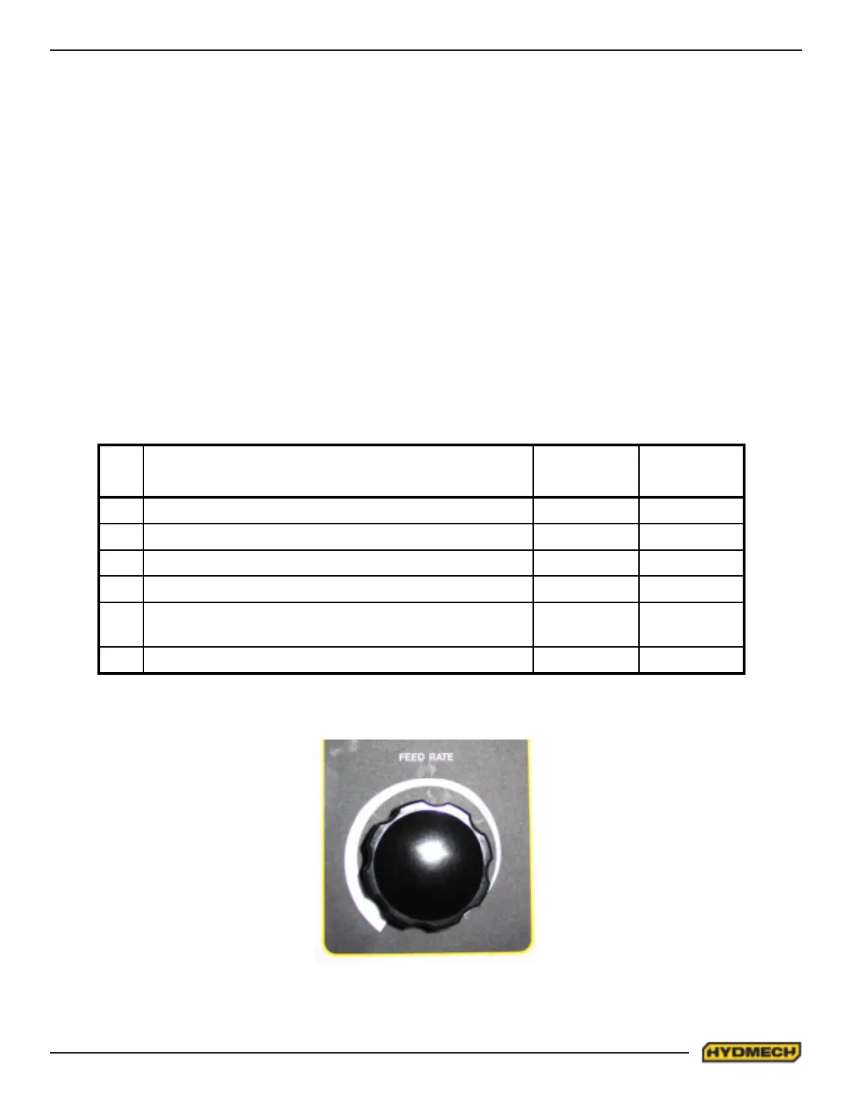
STEP 5 - DETERMINE FEED RATE SETTING, FR (in/min) (mm/min).
NO. Materials
Optimum
Blade Speed
ft/min
Optimum
Blade Speed
m/min
1 5" (125mm) diameter solid medium carbon steel 225 70
2 10" (250mm) I-Beam 270 90
3 4" x 4" (100mm x 100mm) Rect tube 1/4" (6mm) wall 325 110
4 4" 9100mm) 400 stainless steel 140 45
5
2" x 2" (50mm x 50mm) Rect tube 1/4" (6mm) wall
bundle 5 x 5 pcs 10" x 10" (500mm x 500mm)
300 100
6 3" x 3" (75mm x 75mm) Inconel 60 20
In Example #1
• 8” (200mm) diameter #1045 Medium Carbon Steel solid bar is to be cut.
• On the graph above nd the Medium Carbon Steel Curve which represents the optimum blade speeds for 1045
Carbon Steel.
• On the horizontal axis (eective material width axis) nd number 8 which represents eective material width of an
8” (200mm) diameter solid.
• Find the point where a vertical line from 8” (200mm) intersects the Medium Carbon Steel Curve.
• From this intersection point run horizontally left to the vertical axis (optimum blade speed axis) and nd the point
marked “200”.
• For 8” (200mm) diameter, 1045 Carbon Steel solid bar 200 ft/min (60m/min) is the optimum blade speed.
NOTE:
Higher than optimum blade speed will cause rapid blade dulling. Lower than optimum blade speeds reduce cutting rates
proportionately and do not result in signicantly longer blade life except where there is a vibration problem. If the blade vi-
brates appreciably at optimum speed as most often occurs with structurals and bundles, a lower blade speed may reduce
vibration and prevent premature blade failure.
Material Hardness - The graph on the previous page illustrates blade speed curves for materials of hardness 20 RC (225
Bhn) or lower. If the material is hardened then the multipliers need to be used. These multipliers are given in the NOTE at
the bottom right of the graph. As the hardness increases the optimum blade speed decreases.