3.5
BLADE HEIGHT ADJUSTMENT
At the bottom of the head’s stroke the blade must be below the table wear strip in order to complete a cut. To be adjusted
correctly, there should be no light seen between the blade and wear strip. To adjust the blade height, the head cylinder rod
eye is adjusted as described.
Begin by rst lowering the head to the bottom of it’s stroke and moving the guide arm to it’s fully open position. Remove
the feed rate cover and cable near the top of the cylinder.
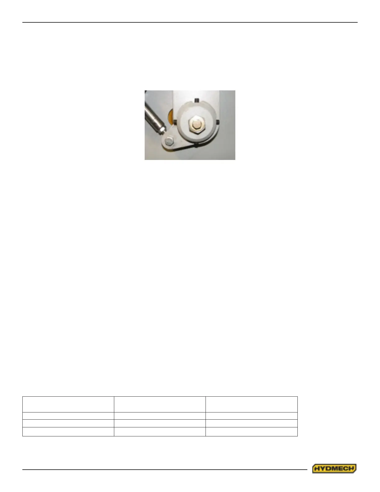
Then loosen the hex nut and turn the cylinder rod using a wrench on the cylinder rod ats (below the top of the feed rate
bracket).
Turning clockwise will raise the blade and turning counter clockwise will lower the blade. The blade must not be lowered
so far as to touch the out-feed table.
When the blade is properly positioned, tighten the hex nut and mount the feed rate cable and cover.
GEARBOX LUBRICATION
The Bonglioli A412 gearbox used on the M16 is supplied with 5.0 litres (1.32 US gallon) of Mobil SHC 630 synthetic oil.
This oil has an ISO Viscosity Grade of 220 that is optimum for ambient temperatures from
10 – 40 Deg C [70 – 104 Deg F]. If the machine will be operated for prolonged periods at ambient temperatures below
20 Deg C [70 Deg F] an oil of ISO Viscosity Grade 150 should be substituted.
The Bonglioli A503 gearbox used on the M20 is supplied with 8.4 litres (2.22 US gallons) of Mobil SHC 634 synthetic oil.
This oil has an ISO Viscosity Grade of 220 that is optimum for ambient temperatures from 20 – 40 Deg C [70 – 104 Deg
F]. If the machine will be operated for prolonged periods at ambient temperatures below 20 Deg C [70 Deg F] an oil of ISO
Viscosity Grade 150 should be substituted.
The suggested oil change interval is given below:
Oil Temperature
Deg C [Deg F]
Mineral Oil Interval
[hours]
Synthetic Oil Interval
[hours]
< 65 [< 150] 8000 25000
65 – 80 [150 – 175] 4000 15000
80 – 95 [175 – 200] 2000 12500
IDLER WHEEL ADJUSTMENT
Remove the cover on the front of the idler end of the head to reveal the horizontal pin. There are four set screws; “A” set
screws should not be adjusted as they are the pivot points. Set screws “B & C” are adjusted by turning one out, the other
in 1/4 turn and tightening the rst again. Adjustments should be made with the blade tension released slightly, 1/4 turn at
a time and checking the blade movement with each adjustment by running the blade at minimum speed. Loosening “C”
and tightening “B” will push the blade off the wheel. Loosening “B” and tightening “C” will pull the blade onto the wheel.
B
A
C
A