Page 31
Collective fault reporting includes the following fault messages:
• “blow-down fault”
• “fault filling”
• “maintenance” (only with electrode steam humidifiers)
• “fault main cont.”
• “fault thermo sensor” (only with unit Type HeaterLine)
The switching signal which switches over the base relay may be
modified using Parameter E5. For an overview of possible fault
messages, see Section: “Summary Table of Parameters”
description of Parameter E5.The factory setting for the switching
signal is “collective fault.”
4.4.4.2 Humidification signal
The humidification signal can be accessed directly on the main
contactor as specified in the wiring diagram.
4.4.4.3 Signal Output
On the main PCB, a signal output is located at terminals 12 (+)
and 13 (-).This output operates according to the set control
mode as follows:
• If an external control signal is used (0 (2) - 10 V DC, 0 (4)
- 20 mA DC, 0 - 140 Ohm), a proportional 0-10 V DC sig-
nal from the external control signal is displayed.
• If an PI-controller is used (= an active humidity sensor is
connected), then the internal control signal of the humidi-
fier is displayed as a proportional 0 - 10 V DC signal.This 0
-10 V DS signal can be used as „external control signal“
for further humidifiers.
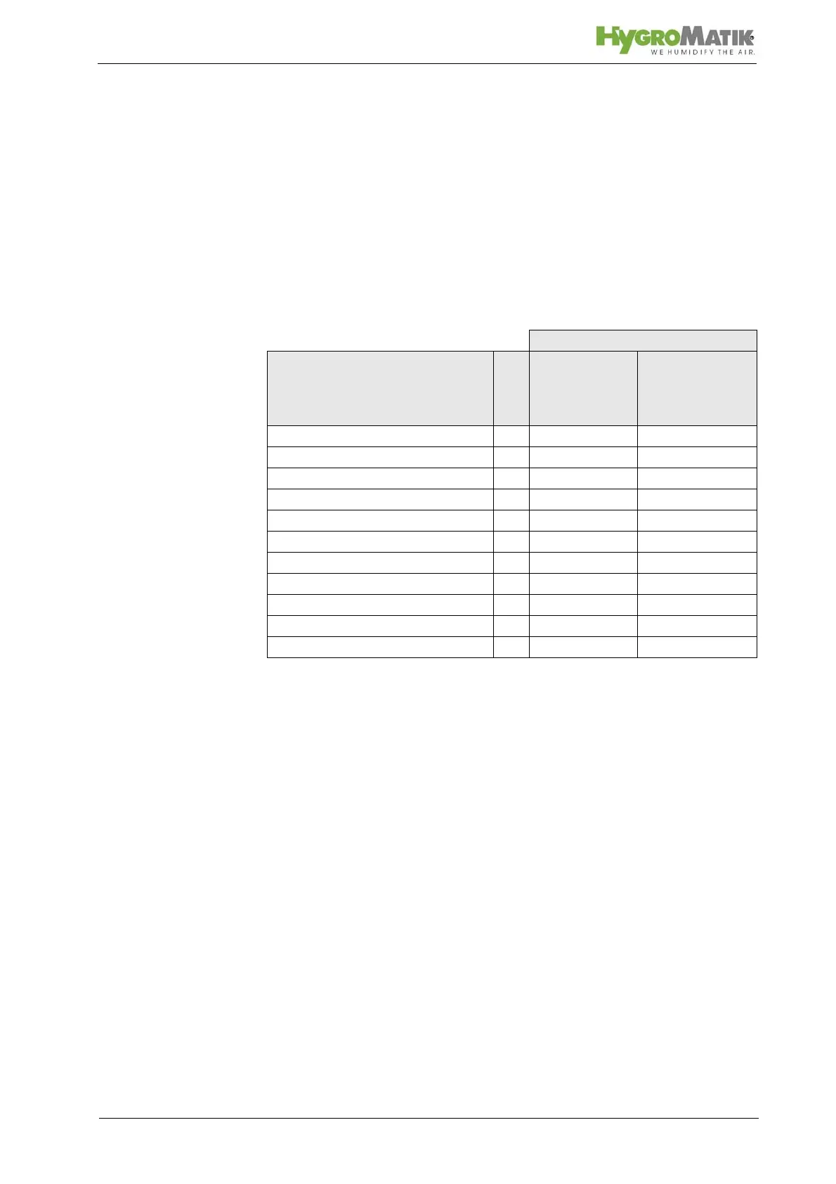
Unit Type
Fault Name
HyLine,
CompactLine,
MiniSteam
HeaterLine,
HeaterCompact
Blow-down fault F1 x x
Thermo sensor activated F2 x
Max.-level F3 x
Fault filling F4 x x
RH sensor fault (broken line) F5 x x
Fault sensor F7 x
Maintenance F8 x
System failure F9 x x
Fault main cont. F10 x
Steam-down time F11 x
Lost ground control x x