Page 36
5.2 Signal Relay PCB (Optional)
This option is not available for electrode steam humidifiers type
C01!
Four additional signal relays are available with the optional sig-
nal relay PCB. The possible programmable states for each relay
are:
0= collective fault
1= fault data exchange
2= humidification
3= stand-by
4= max.-level (HL and DL humidifiers only)
5= blow-down fault
6= Maintenance interval exceeded
7= fault filling
8= no demand
10= dehumidification [E18]
11= thermo sensor activated [Fault F2] (HL and DL only)
12= fault main cont.
17= Super Flush
18 = maintenance (electrode steam humidifiers only)
*Only with control type “proportional control with integrated soft-
ware controller”
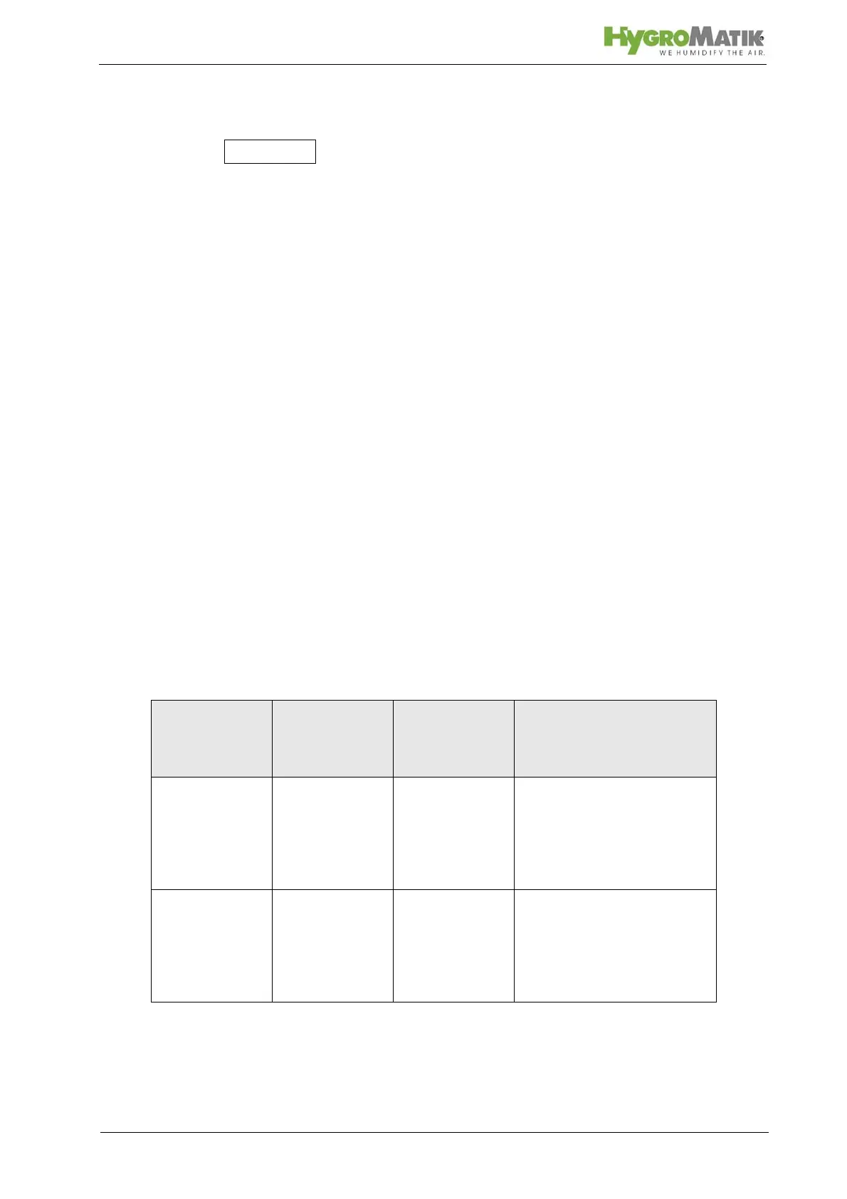
Connections 31 to 42 are located on the signal relay PCB. The
assignments are as follows:
Signal Relay /
Contact
Contacts Parameter for
Selecting
Switching Sig-
nal
Factory Setting for
Switching Signal
1. Signal Relay
Normally Closed
Contact
Normally Open
Contact
31, 32, 33
32
33
E6 Humidification
2. Signal Relay
Normally Closed
Contact
Normally Open
Contact
34, 35, 36
35
36
E7 Stand-by