Page 80
11. Wiring Diagram
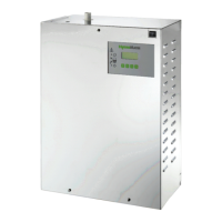
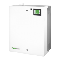
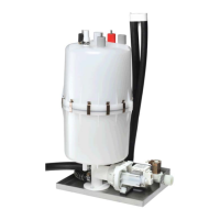
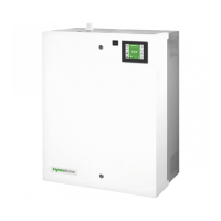
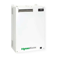
Steam Humidifier
28 - 30 signal relay (collective fault)(ST4) B1 sensor electrode
31 - 42 optional: 4 signal relay ouputs (see JP3) F1 controller fuse 1.6 A
JP1 jumper terminal basic settings K1 main contactor
ST 8 connector COM-Port L1-L3 main terminal
ST 9 connector remote control M1 blow-down pump
JP 9 / JP 4 jumper socket interface driver M2 motor fan (MiniSteam only)
JP 5 socket display S1 control switch
Off Pos. 0 On Pos. I/
Abschlämmen Po. II
JP 3 jumper socket signal relay Y1 solenoid valve
Y2 solenoid valve for flushing mecha-
nism
1-2 terminals for hygrostat and safety
interlock
4-5 terminals for external control sig-
nal
3 24V