Änderung Datum Name
Bearb.
Gepr.
Norm
Datum
Urspr. Ers.dErs.fZust.
Blatt 1
von 2 Bl.
(Zeichnung Nr.)(Benennung)
(Datei)
S-042901-1
S-042901D.001
HYGROMATIK
Lise-Meitner-Str. 3
D-24558 Henstedt-Ulzburg
Saksan liittotasavalta
/
Germany
Telefax
+49-(0)4193 / 895 - 33
Phone
+49-(0)4193 / 895 - 0
03.11.04
Hn
ST3
4
(-)
X1
2
1
Y1
M
M1
ST1
13
12
16
111092
5
3
4
42
S1b
F1
S1a
15
28 3029
ST2
28 3029
6
7
18
17
K1
22
21
ST6
23 24
G3
G2
G1
1,6AF
b
d
Y2
ST5
ST4
ST7
K1
1
2
3
4
5
6
L1 L2 L3N
PE
1
L1
R1
5
4
L2
21
L3
3
PE
X1
HL6 - HL45 400/3/N/50Hz
3
+24V
7
8
-
+
-
+
3+24V,4(-),5(+) 03.01.06 Lue
5
(+)
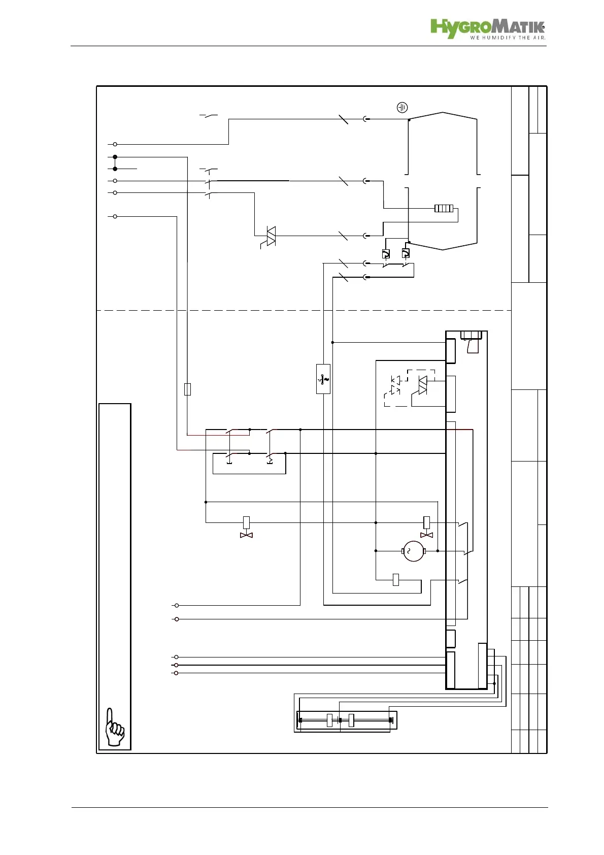
interlock system
Basis Platine / basic electronic
Eingang Regler / Fühler
rot/red - G2
blau/blue - G3
schwarz/black
weiß/white - G1
R1 : HL6 4,5 KW Heizkörper / heater element
signal humidification
for HL 6 -45
fürHL6-45
control stage
Steuerungsteil
for HL 6 -9
fürHL6-9
power stage
Leistungsteil
located at middle plate
an Gerätemittelwand
solid stat e r ela y
Halbleiterrelais
solidstaterelay(2inHL30-45)
Halbleiterrelais (2 in HL 30-45)
thermo switch for each
Thermowächter
(twice in HL 30-45)
(doppelt in HL 30-45)
solid state re lay
Halbleiterrelais
- parallel zur Pumpe M1
-paralleltopumpM1
Super Flush Y2
Sicherheitskette
input sensor
G2-Betriebsniveau
G3-Max. Niveau
dry level
G1-Trockengang
operational level
max. level
Schwimmerschalter
sensor levels
R1 : HL9 6,75 KW Heizkörper / heater element
Meldung Befeuchten
HL 12 - 45: Leistungsteil / pwr stage: S-042901-6
25
STB 2 12.11.12 Lue
2
c
Klemme 25 25.03.09 Pn
Note: The steam humidifier is only operationable if the contact
across terminal 1 and 2 (the safety interlock) is closed.