MAINTENANCE
5-18 HPR130 Manual Gas Instruction Manual
6
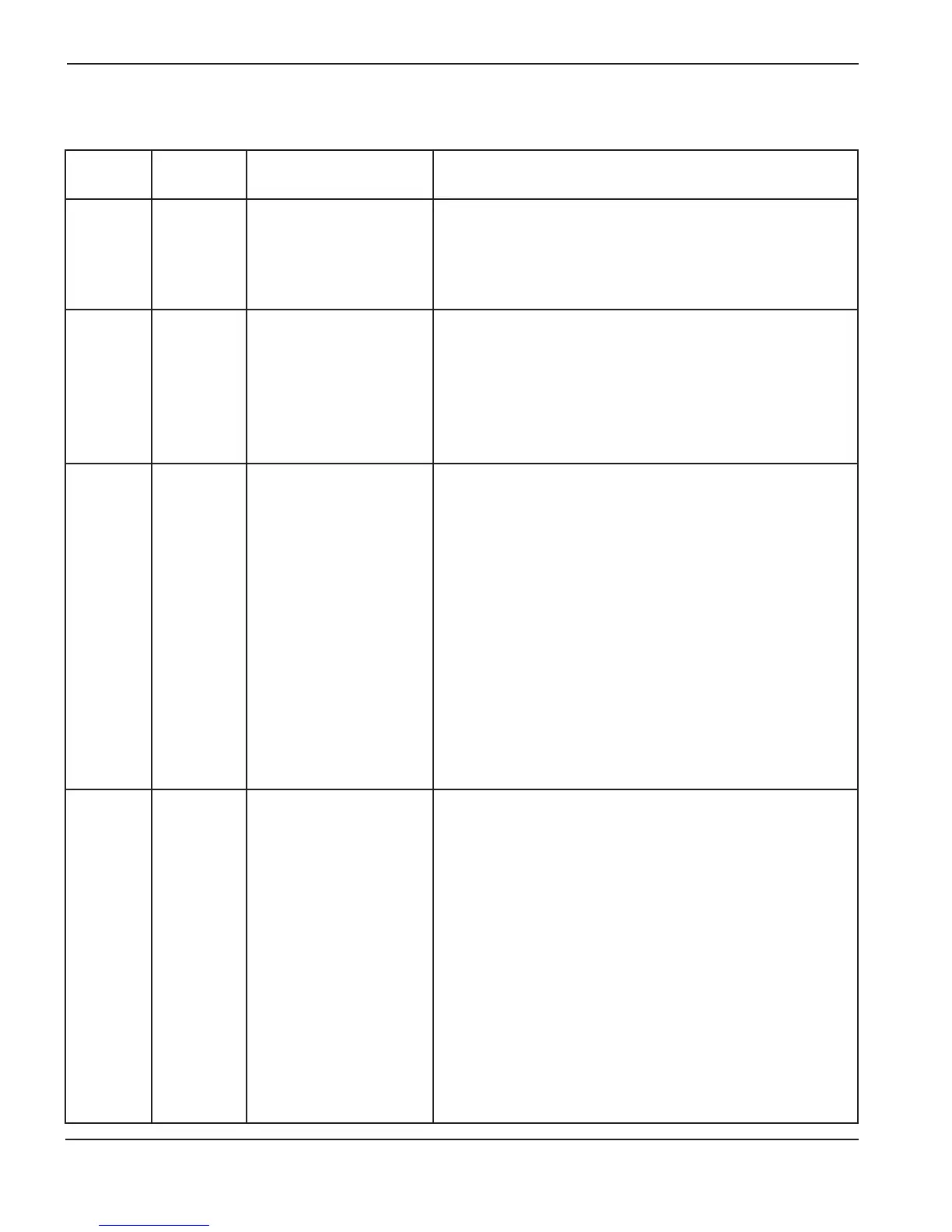
Error code troubleshooting – 8 of 10
Error code
number
Name Description Corrective action
123
MV1 error
Auto Gas
Only
Motor valve 1 did not
move into position within
60 seconds.
1. Verify that LED D17 or D18 illuminates on the AC valve
driver PCB in the selection console. If either illuminates,
replace the motor valve. If they do not illuminate, replace
PCB3.
124
MV2 error
Auto Gas
Only
Motor valve 2 did not
move into position within
60 seconds.
1. Verify that LED D19 or D20 is illuminating on the AC valve
driver PCB in the selection console. If either illuminates,
replace the motor valve. If they do not illuminate, replace
PCB3.
133
Unknown
gas console
type
The power supply control
board does not recognize
the gas console that is
installed or has not
received a CAN message.
1. Verify that the part numbers of PCB2 and PCB3 are correct.
2. Verify that cable number 5 (power supply-to-gas console
control cable) is not damaged and is properly connected to
PCB3 and the rear of the gas console.
3. Verify that cable number 6 (power supply-to-gas console
power cable) is not damaged and is properly connected
inside the power supply and to the rear of the gas console.
4. Verify that D1 (+5 VDC) and D2 (+3.3 VDC) are illuminated
on PCB2 inside the gas console. These LEDs indicate
power to PCB2.
5. If power is present at PCB2 and PCB3 and both gas
console cables are good, then PCB2 or PCB3 has failed.
Use the CAN tester to verify which board needs to be
replaced.
134
Chopper 1
overcurrent
Chopper 1 current
feedback has exceeded
160 amps.
1. Verify that the wiring between CS1 and PCB3 is correct
and not damaged.
2. Measure voltage across current sensor.
a) Red to black = +15 VDC, Green to black = -15 VDC,
white to black = 0 VDC at idle and varies with current
output (4 VDC = 100 amps).
b) If possible, take a voltage reading on current sensor while
trying to cut. Ratio is 4 VDC = 100 amps.
c) If the current sensor voltage is approximately 6.4 VDC or
greater at idle, replace the current sensor.
3. Remove connector J9.1 from the chopper and verify that
LED1 is extinguished.
a) If LED1 is extinguished with the connector removed, then
reconnect J9.1 and try to fire the torch. If the chopper still
goes into overcurrent, replace the chopper.
b) If the chopper does not go into overcurrent, replace
PCB3.
 Loading...


