HPR130 Manual Gas Instruction Manual 7-1
Section 7
WIRING DIAGRAMS
Introduction
This section contains the wiring diagrams for the system. When tracing a signal path or ref er enc ing with the Parts List or
Troubleshooting sections, please be aware of the following format to assist you in un der stand ing the wiring diagrams'
organization:
• Sheet numbers are located in the lower right-hand corner.
• Page-to-page referencing is done in the following manner:
C
SHEET
4-D3
C
SHEET
4-D3
Destination and Source Coordinates refer to letters A-D on the Y-axis of each sheet and numbers 1-4 on the
X-axis of each sheet. Lining up the coordinates will bring you to the source or destination blocks (similar to a road map).
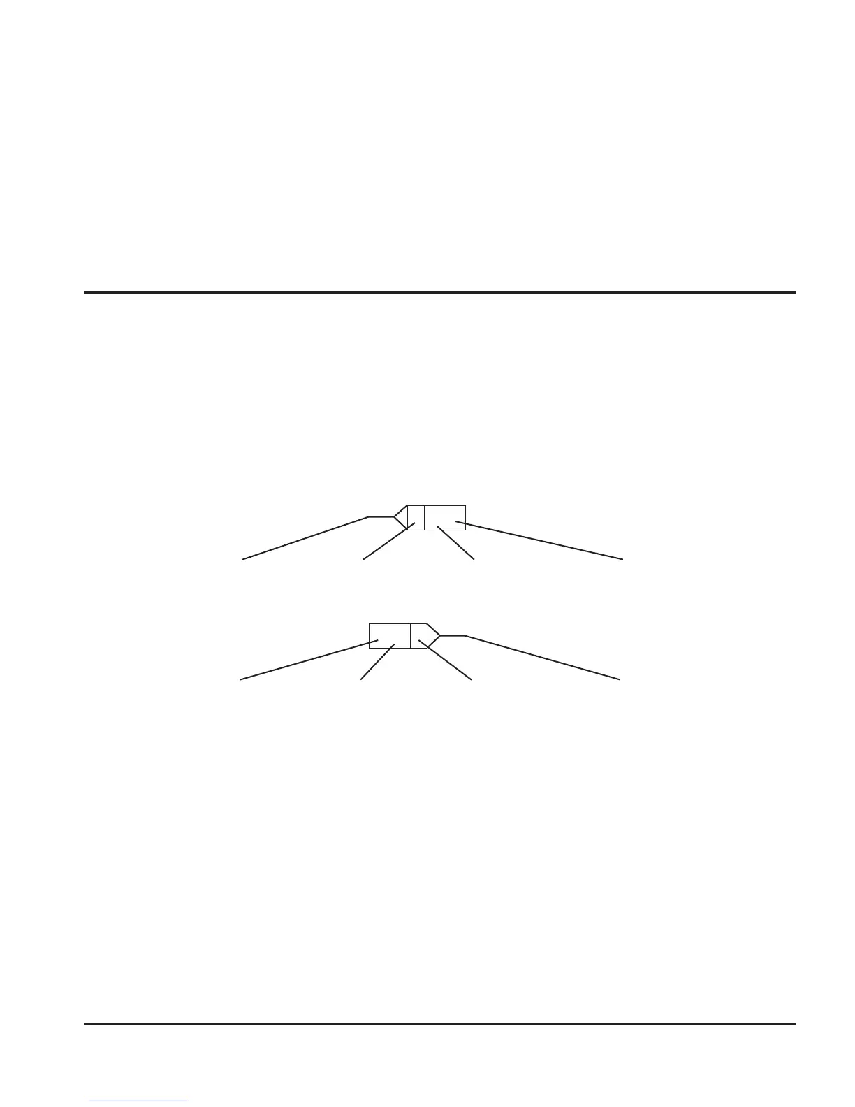
Wiring Diagram Symbols
Wiring diagram symbols and their identification precede the system wiring diagrams in this section.
Source Connection Source Reference Block Destination Sheet # Destination
Coordinates
Source Sheet # Source Coordinates Source Reference Block Destination
Coordinates

 Loading...


