0
PARTS LIST
HPR130 Manual Gas Instruction Manual 6-3
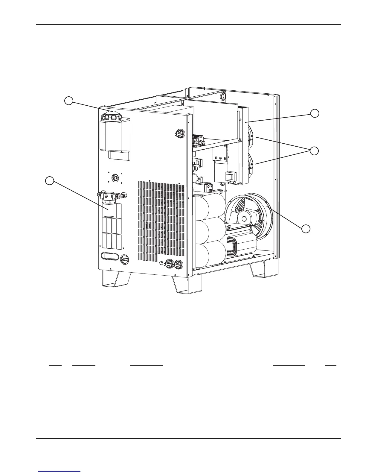
Power supply
Part
Item Number Description Designator Qty.
1 027634 Filter housing 1
027664 Filter element 1
2 127014 Cap: coolant resevoir 1
3 129792 Chopper assembly CH1 1
4 127039 6" fan :230 CFM, 115 VAC 50-60 HZ 2
5 027079 10" fan :450-550 CFM, 120 VAC 50-60 HZ 1
 Loading...


