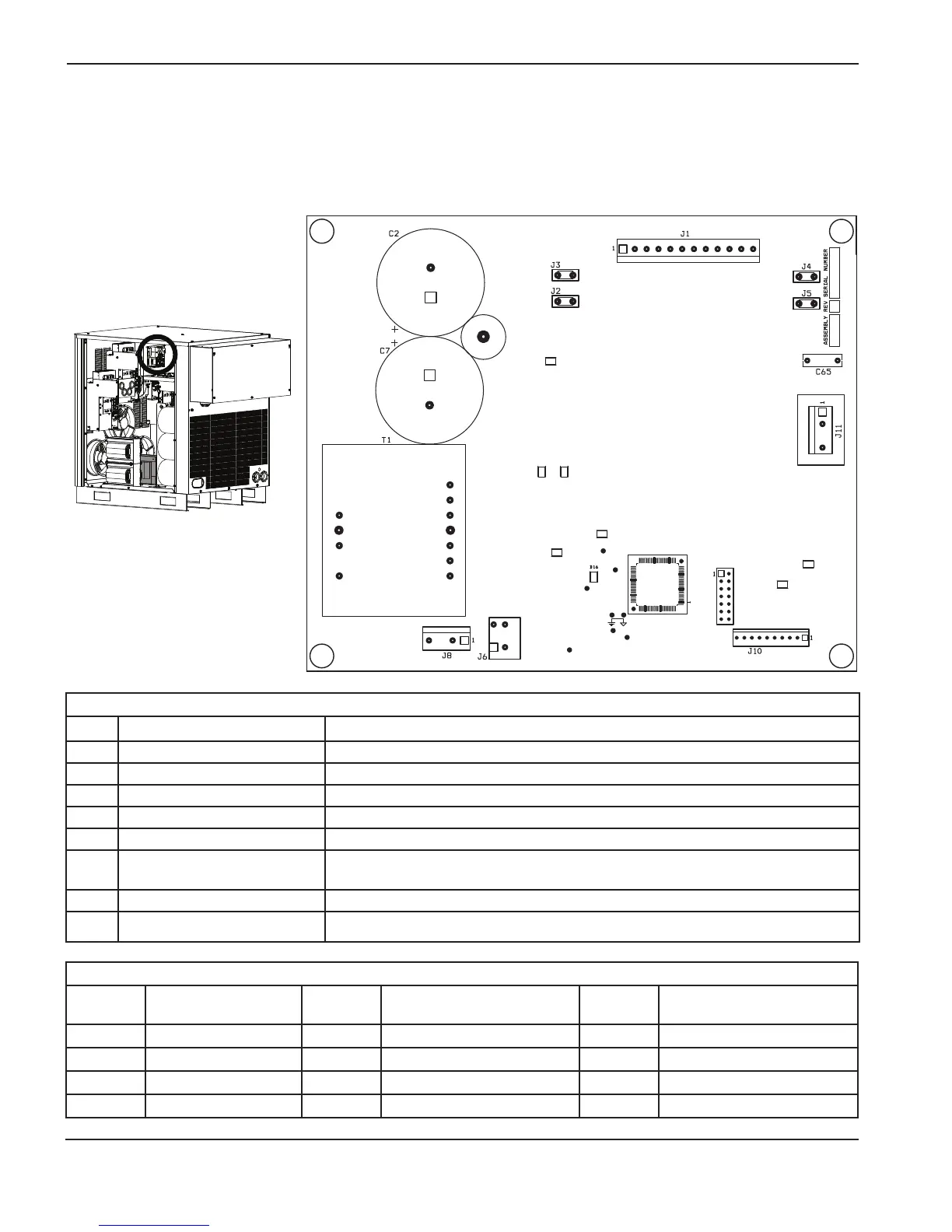
Control PCB test points
Test point
number
Description
Test point
number
Description
Test point
number
Description
TP1 Analog ground TP5 + 5 V TP9 Digital ground
TP2 Digital ground TP6 A + 3.3 V TP10 + 3.3 V
TP3 Reset\ TP7 + 3.3 V TP11 SCIRXD
TP4 Reset TP8 SCITXD TP12 LINEFB +
Control PCB LED list
LED Description Status
D1 + 15 V OK On when +15 voltage is OK
D10 + 5 V OK On when +5 voltage is OK
D16 + 3.3 V OK On when +3.3 voltage is OK
D30 IPM temperature alarm output Off when OK. On when there is a sustained over-current condition
D31 Temperature Off when OK. On when there is a temperature fault
D32 IPM alarm output
Off when OK. On when there is an internal overtemp, over current, or bad gate supply-
drive voltage
D35 Pump motor drive OK On when pump motor drive is OK
D36 Pump motor drive enable On when enabled
Note: The inductor on the pump motor-drive board makes a noise during operation that has been
described as a “hum”, “sing”, and “click”. This is normal and can be disregarded.
 Loading...