© 2023 HyQuest Solutions 15
Installation
2.4.4 Digital Inputs
The two digital inputs are jumper selectable for either mechanical or electronic operation. In either case it is necessary to
pull the input down to 0 V DC to activate it. Inputs will handle up to 30 V DC in the off state for parallel connection across
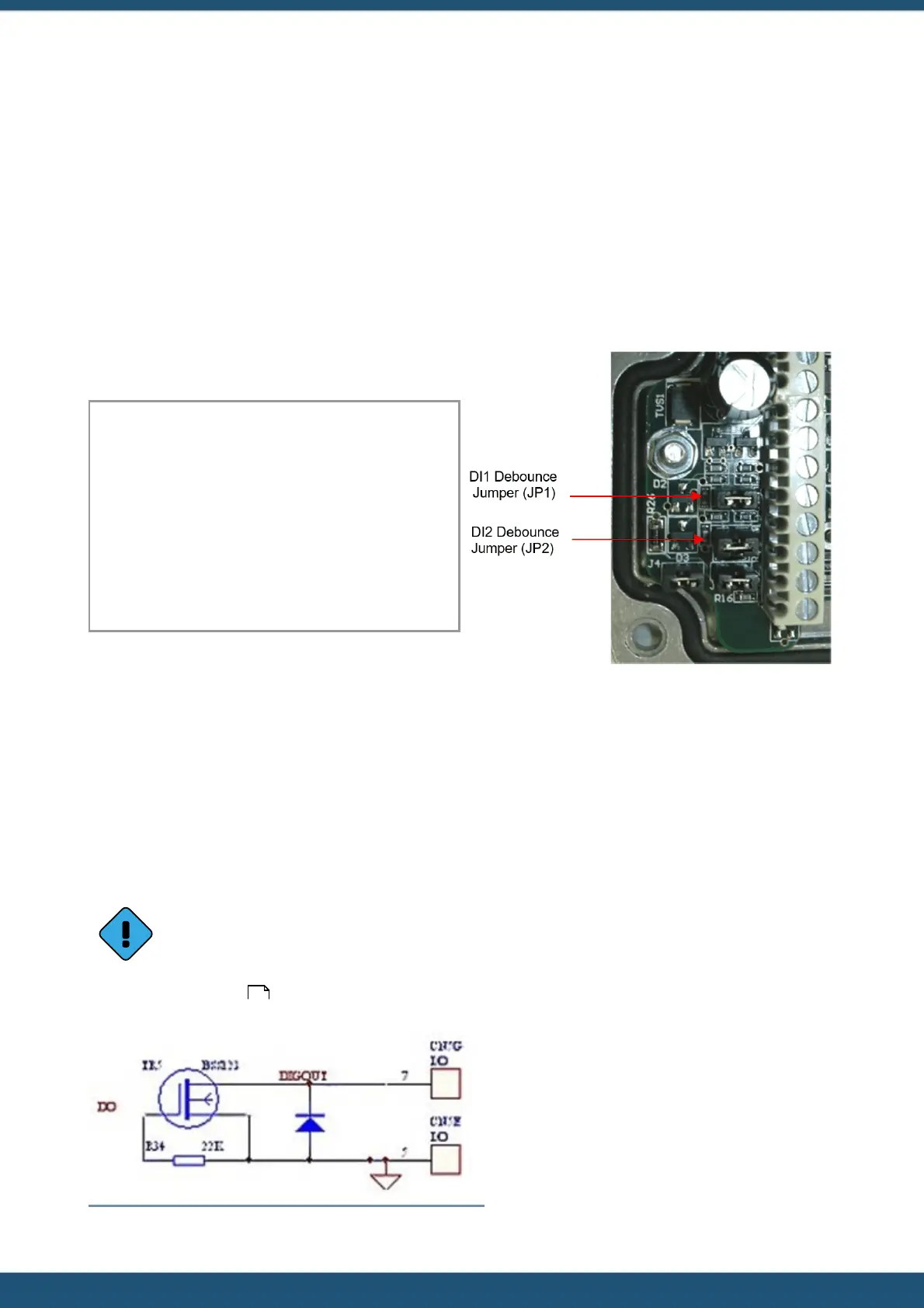
existing equipment. Jumpers are positioned to the left hand side of the I/O connector. The top jumper is for Digital Input
#1 and the middle jumper is for Digital Input #2.
Fit the jumper for mechanical switching at up to 20 Hz. In this mode a 100 nF capacitor is fitted across the input to
provide limited hardware debounce, preventing false triggering due to contact bounce. Remove the appropriate jumper
for electronic switching at up to 5 kHz.
Hint: If removing a jumper, simply fit it to one pin only of the connector to avoid it being lost.
Important Note:
In almost all installations where an iRIS is connected in
parallel with other equipment to share a common pulse
input (e.g. from a flow meter), there has not been a
detrimental effect, as the iRIS inputs present a relatively
high impedance to the circuit. However, in the event that
connecting an iRIS does cause pulse failure, HyQuest
Solutions recommend removing the debounce selection
link for the appropriate input. This sets the input to
electronic switching mode, even if the actual pulse source
is a clean contact (reed switch or similar).
Figure 2 – Digital Input Debounce Jumpers
2.4.5 Digital Output
The Digital Output is open drain pull-down and is capable of sinking up to 300 mA at 30 V DC. Typically this could be used
to drive a relay powered by an auxiliary DC supply (e.g. 12 V). In this mode, the negative of the relay supply must be
connected to one of the iRIS GND terminals.
The output can be programmed to follow a schedule for use in powering external sensors / circuits, or operate in
response to alarm activation from any of the sensors.
On the iRIS 150FXC variant, the digital output also controls the switched +Vin supply voltage. When the digital
output is activated, the supply voltage on +Vin is switched to the SWV terminal and can be used to power
external loads without the need for a separate transistor switch.
See Section Digital Output for details on the digital output modes.
Figure 3 – Digital Output Circuit
30
 Loading...