© 2023 HyQuest Solutions 20
Installation
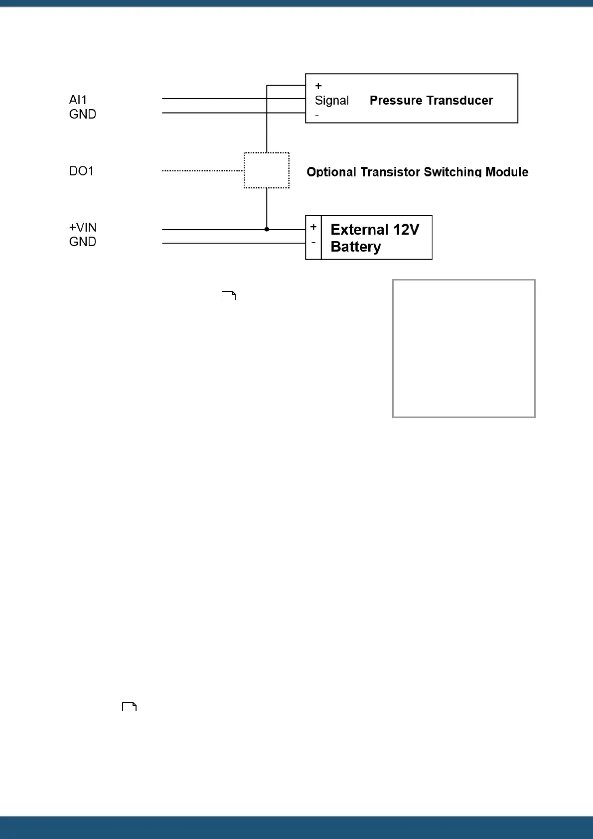
The sensor should be configured for the correct channel, scaling and logging
regime as described in Section Sensors . A typical sensor configuration
example for this type of instrument is shown below. The instrument is a 10
metre, 0 - 5 V output pressure transducer. The level is averaged and the result
logged every 15 minutes.
Name: Water Lvl
Source 1: Analog In 1
Process Mode: Period
Average
Multiplier: 2.000
Offset: 0.0000
Log Rate: 15 mins
Note: The iRIS supports activation of the digital output with a schedule. Therefore, if further power reduction is to be
achieved by controlling the transducer power, follow this procedure:
1. Install a transistor switch module in series with the transducer power lead and control it from the digital output.
2. Configure the digital output’s mode to be Schedule (Mode = 0).
3. Set up the digital output’s schedule to match the sensor’s logging period, but with the digital output being set to
activate the desired amount of time before the sensor is to log and with sufficient “on” time to ensure an overlap with
the logging time.
4. Ensure the sensor mode is set to 0 (Instant).
2.5.4 Connecting a 2-Wire Loop-Powered 4-20mA Sensor
The iRIS also supports the connection of many types of industry standard 4 - 20 mA current loop instruments such as
ultrasonic or radar level sensors. A very common configuration used with these devices is known as two-wire or loop-
powered mode. This requires only two wires to the sensor and the 4 - 20 mA loop current provides power for the sensor
as well as being the proportional analogue sensor signal.
These sensors often require a minimum voltage across them that may not be reliably achieved with a 12 V supply, taking
into account the voltage drop across the sense resistor. In such cases, a separate 12 - 24 V boosted sensor supply is
recommended.
The diagram below shows the recommended connection diagram for such an installation. It assumes the use of AI1 as the
desired input channel.
The iRIS has an internal 250 Ω sense resistor that can be enabled by the use of jumpers J3 (AI1) and J4 (AI2), see section
Analogue Inputs for more information. The internal sense resistor generates a 1 - 5 V signal (from the 4 - 20 mA
current), which is then measured by the analogue input.
32
14
 Loading...