© 2023 HyQuest Solutions 16
Installation
2.5 Sensor Connection Examples
This chapter contains the following subsections:
§
Connecting a Flow Meter or Rain Gauge
§
Simulating a Flow Meter using Auto-Pulse mode
§
Connecting a 0 - 5 V Pressure Transducer
§
Connecting a 2-Wire Loop-Powered 4-20mA Sensor
§
Measuring the External Supply Voltage
§
Connecting SDI-12 Instruments
§
Connecting an Up/Down Water Level Instrument
§
Connecting Analogue Wind Instruments
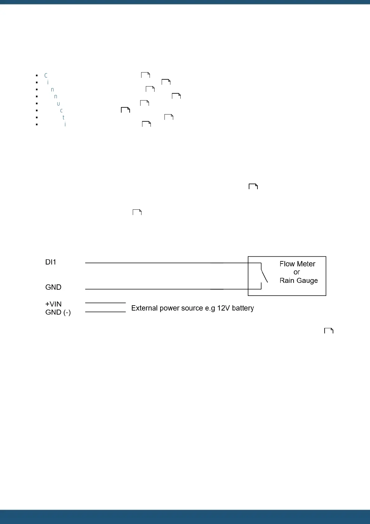
2.5.1 Connecting a Flow Meter or Rain Gauge
One of the most common uses for the iRIS is logging data from pulse sources such as flow meters or rain gauges.
Connecting such devices to the iRIS is very simple – wire the switch between the appropriate digital input (DI1 or DI2) and
a ground (GND) terminal. Both of the digital inputs provide a “wetting current” for clean contact sources, but transistor
switches and active signals (ones that supply a voltage) can also be used. If a transistor switch is used, connect the
collector (+) to the digital input and the emitter (-) to the GND. See Section Digital Inputs for details on the digital inputs
and using the debounce link.
Both inputs can be used simultaneously and each input has three associated totalisers, which are viewable from the LCD.
See Section Totals Screens (DI1 and DI2) . These totalisers operate even if the input is not configured as a source to one
of the six virtual sensors.
The diagram below shows the typical connection diagram for such an installation. It assumes the use of DI1 as the pulse
input channel. The external power source can be any DC supply from 6 V to 15 V.
The sensor should be configured for the correct channel, scaling and logging regime as described in Section Sensors .
Event mode (Sensor Mode = 2) can be used to reduce the quantity of data logged, especially for rainfall where the actual
data density is low.
Three typical sensor configuration examples for this type of instrument are shown below. The instrument is a 0.5 mm
tipping bucket rain gauge (TBRG) and is logged every 15 minutes for examples 1 and 2.
16
19
19
20
21
23
23
24
15
51
32