© 2023 HyQuest Solutions 24
Installation
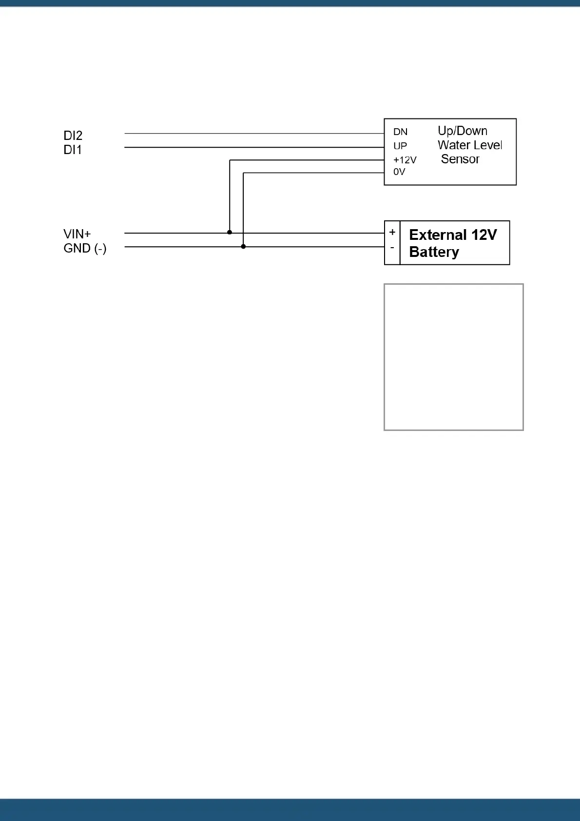
These instruments normally require a 12 V supply, which can also be used to provide external power to the iRIS.
The diagram below shows the required connections for such an installation. The incrementing output must be connected
to DI1 and the decrementing output to DI2.
A typical sensor configuration example for this type of installation is shown
below. The instrument is a standard digital up/down water level encoder. The
level is averaged and the result logged every 15 minutes.
Name: Water Lvl
Source: 9. Up/Down
Encoder
Process Mode: Period
Average
Multiplier: 0.001
Offset: 0.000
Log Rate: 15 mins
2.5.8 Connecting Analogue Wind Instruments
There are a number of wind speed and direction instruments available that interface relatively easily to the iRIS. This
section describes how to connect typical mechanical wind instruments as provided by manufacturers such as Vector
Instruments Ltd or NRG. The anemometer provides pulses that are measured as a frequency via a digital input. The
potentiometer type wind speed instrument provides a 0 - 5 V signal measured by an analogue input. This however
requires an external regulator to provide the 5 V supply.
The diagram below shows the required connections for such an installation. The wind speed sensor pulse output should
be connected to a digital input (DI1 or DI2) and the wind direction sensor connected to an analogue input (AI1 or AI2).
Note also that some wind speed instruments (e.g. the Vector A101M) may require external resistors to suitably bias the
internal electronics. Refer to the manufacturer’s data sheet for details and the appropriate multipliers and offsets that will
be needed.
 Loading...