© 2023 HyQuest Solutions 54
Operation
4.5.1 Example: A 4 - 20 mA Flow Meter
In this example, we have a flow meter connected to the iRIS Analog Input 1. The meter is configured to provide a 4 - 20
mA signal for a 0 - 100 l/s flow range. The internal current sink resistor in the iRIS is 250 Ω (theoretically giving 5 V at 20
mA). However, there is a small reduction in actual resistance caused by the paralleled internal input impedance of the iRIS
input channel to take into account (see Section Analogue Inputs ). Therefore the voltage measured by the iRIS for a
given water level is slightly different.
1. Power up the installation and allow it to stabilize.
2. Set the meter to zero flow (4mA signal) using its internal simulator function.
3. Note the actual voltage measured by the iRIS (view this on the LCD on the I/O summary screen). See Section I/O
Summary . The LCD screen example below shows 965 mV for a 0 l/s flow rate.
4. Now increase the meter to full scale (100 l/s, 20 mA) using its internal simulator function. Again, note the measured
voltage relating to this input level. This time it is 4891 mV for a 100 l/s rate.
AI1: 965 mV
AI2: 0 mV
DI1: 0 DI2: 0
DO: 0 SDI: 0
AI1: 4891 mV
AI2: 0 mV
DI1: 0 DI2: 0
DO: 0 SDI: 0
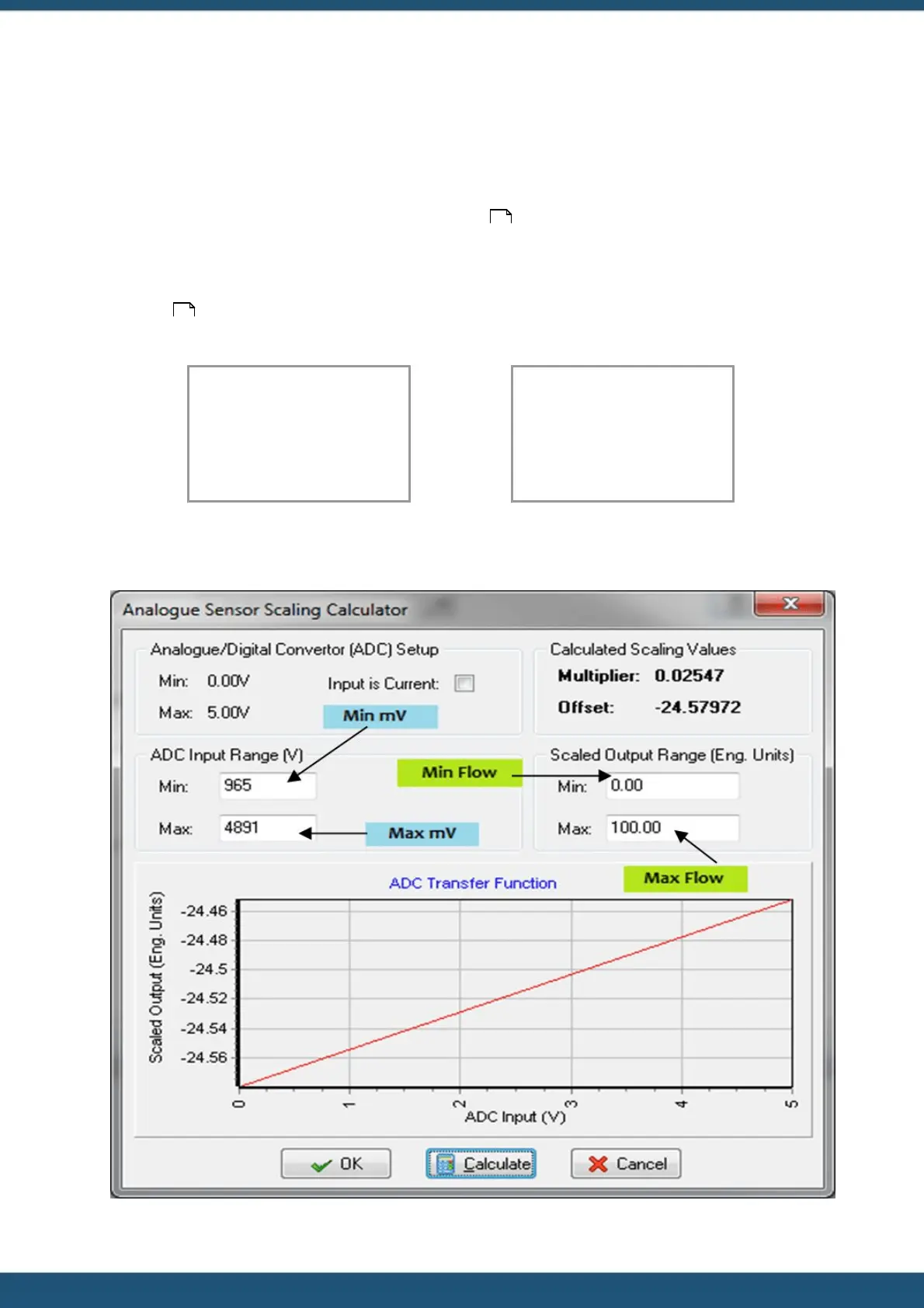
5. Using the iLink 2012 Scaling Calculator, enter the minimum and maximum measured voltages and the flows they
represent in the appropriate fields. Click the “CALCULATE” button to generate the correct multiplier and offset
parameters to use in the sensor setup menu for Sensor 1 as shown.
14
50
 Loading...