© 2023 HyQuest Solutions 19
Installation
2.5.2 Simulating a Flow Meter using Auto-Pulse mode
Occasionally a flow measurement is required and there is no flow meter available. If the flow rate is relatively constant
and/or accuracy is not critical, it is possible to simulate a flow rate by using the “Auto-Pulse” sensor source type.
When this source type is used, the iRIS will simulate a pulse rate of once-per-second (1 Hz) while the associated digital
input is on (active). By setting the multiplier to define the rate in units per second, the iRIS will accumulate and log the
value just as if it were obtained from real pulses from a physical flow meter.
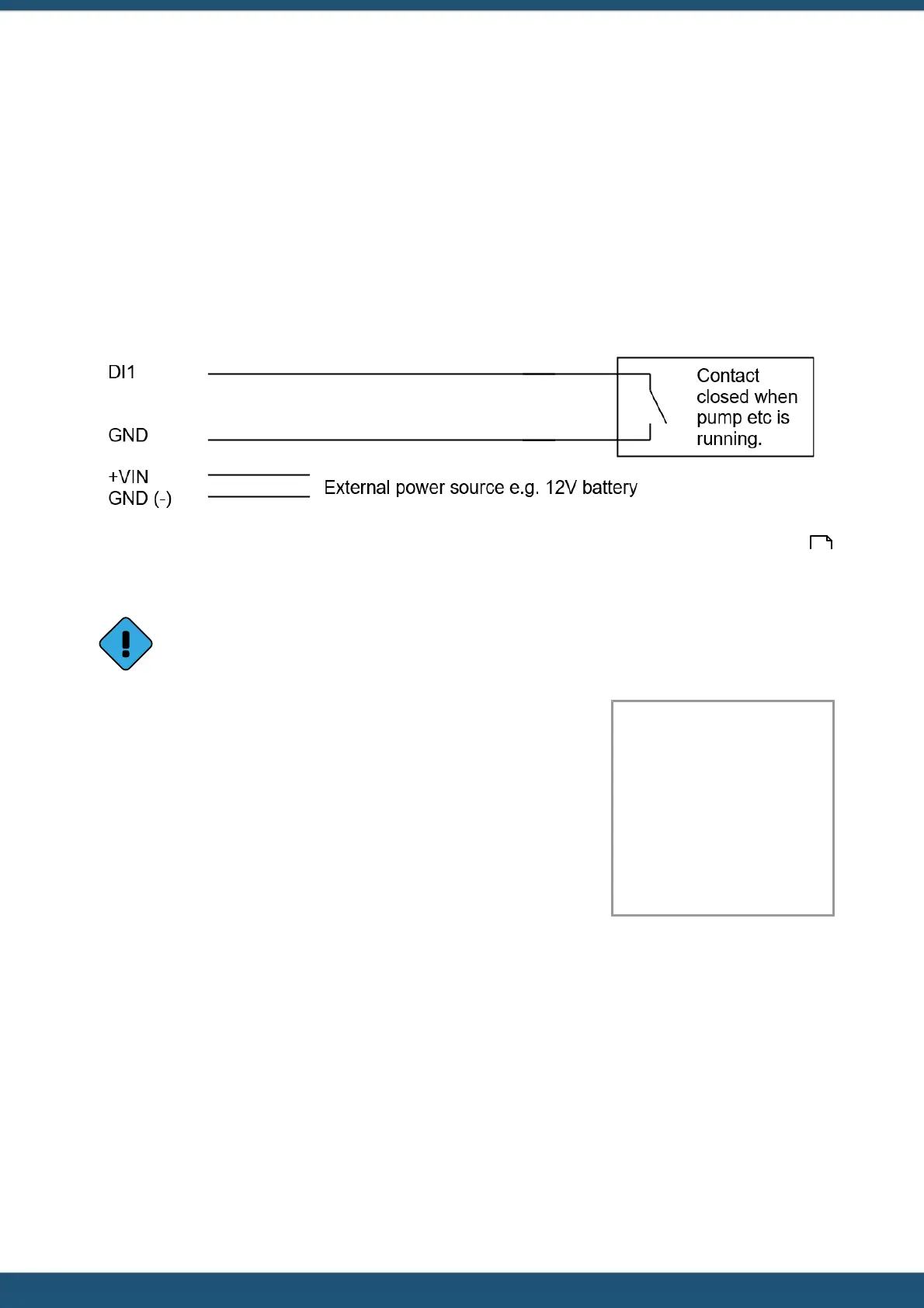
The diagram below shows the typical connection diagram for such an installation. It assumes the use of DI1 as the device
(pump etc) run status input. Typically this would be from a volt-free contact on an auxiliary relay that is enabled when the
pump is running. The external power source can be any DC supply from 6 V to 15 V.
The sensor should be configured for the correct channel, scaling and logging regime as described in Section Sensors .
Event mode (Sensor Mode = 2) can be used to reduce the quantity of data logged, especially for intermittent operation
where the actual data density is low.
This mode is also useful for other applications such as accruing run-times of machinery or active time on
radio channels by monitoring the busy status on a radio. In either of these cases, the multiplier is typically 1,
giving an accumulated value in seconds.
This example accrues pumped volume in m
3
at a simulated pumping rate of 17
l/s (0.017 m
3
/s) while DI1 is active.
It logs the accumulated volume total every 15 minutes to two significant places,
even if it is zero. This produces the most data as every “time slot” has an
associated sample.
Name: Volume
Source: 5. Auto Pulse
1
Process Mode: Instant
Multiplier: 0.017
Offset: 0.0000
Log Rate: 15 mins
2.5.3 Connecting a 0 - 5 V Pressure Transducer
Connecting a standard sensor (such as a pressure transducer that provides a 0 - 5 V signal) to an iRIS is relatively
straightforward. An external 12 V battery (7 A/Hr or larger) is required to power the sensor but this can optionally be
controlled by the iRIS’ digital output to save power.
The diagram below shows the typical connection diagram for such an installation. It assumes the use of AI1 as the desired
input channel. It also shows the connection of a transistor switch module with control from DO1.
32