Site Overview & Planning
1-2 SlideSmart Installation and Reference Manual Revision D
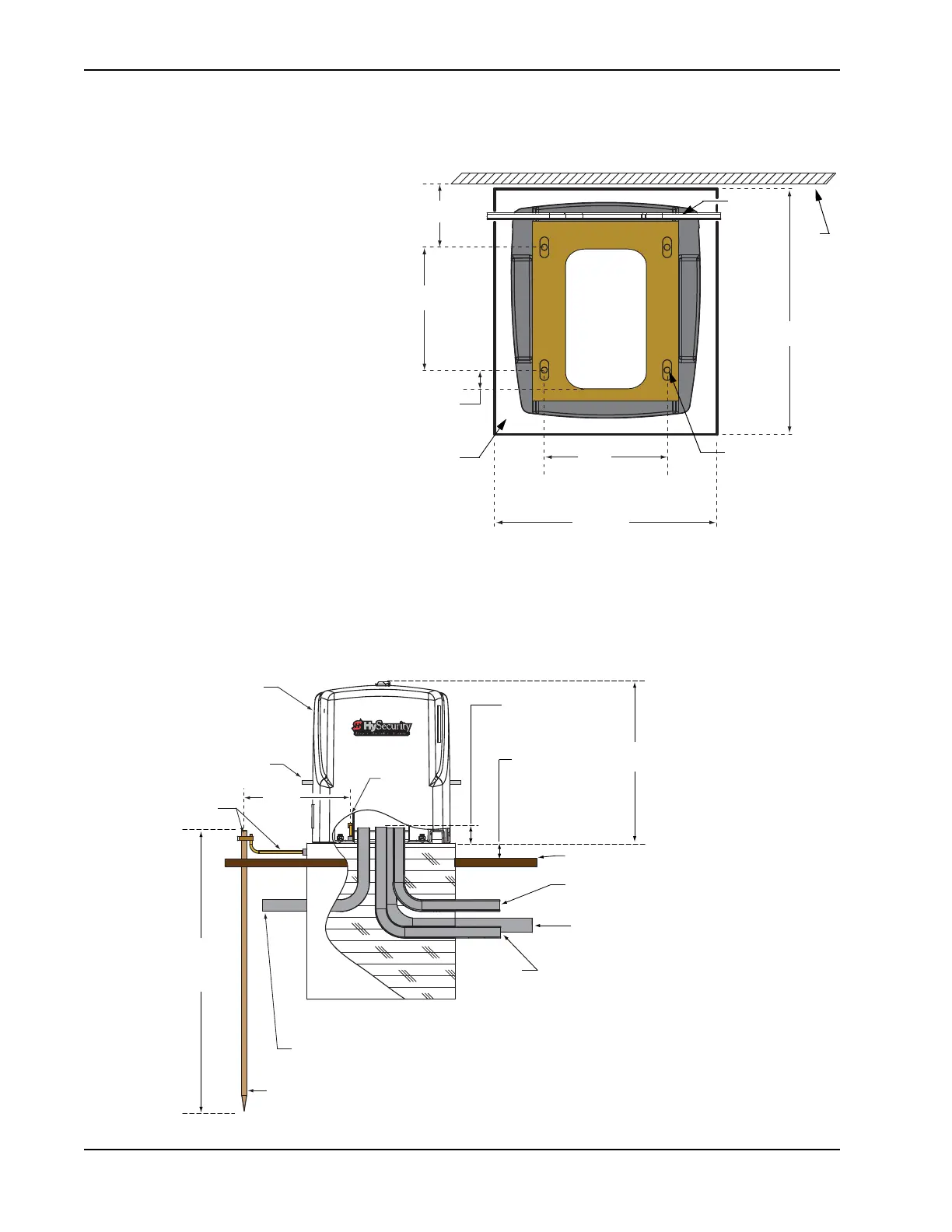
Pad Condition
1. Follow the local building codes to
identify the frost line and determine
the required depth of the concrete pad.
HySecurity recommends a minimum
16-inch depth with a minimum 2-inch
extension above ground level. Refer to
Figure 1-2 and Figure 1-3.
2. Before pouring the pad, consider
conduit placement so it fits within the
confines of the 6.9 x 12-inch cutout in
the SlideSmart base as shown in
Figure 1-2. Run separate conduits for:
• high voltage wiring (115-230V
supply power) including
equipment ground
• low voltage wiring (12V and 24V
accessory power)
• vehicle loop control wiring
• master/slave connections
•earth ground (NEC/NFPA)
3. Extend conduit height 2-inches (5cm) above the pad (4-inches (9cm) above ground level). Make sure the
concrete forms are square with the gate and the pad is level. The operator footprint, with covers, is
approximately an 18-inch square (4.7cm). See Figure 1-2 for the minimum pad dimensions.
19" minimum
(48.3cm)
Area
cut out
for
conduit
6.9 x 12"
(17.5 x 30.5cm)
21"
(53.3cm)
10.5"
(26.7cm)
1.6"
(4.1cm)
6.4"
(16.3cm)
10.38"
(26.4cm)
Figure 1-2.
Chain
#40 Roller
Slotted holes (4x) for
concrete anchors:
½ - 13 x 3½"
Concrete
pad
Gate
Grounding rod depth at
10
(3m) or per local code
Vehicle loop
control wires
Extra conduit
(Master/Slave power)
(Conduit may be shared with low voltage wires)
Low
voltage/Communicaon wires
20.7"
(52.6cm)
Conduit runs
2" (5cm) above
concrete pad
Minimum pad
height is 2" (5cm)
above grade level.
High voltage wires
Main AC power
Cut-away
view
Concrete pad
(depth set per
local codes)
Consult local
codes for
proper depth
3 max.
(91.4cm)
Ground
lug
Chain
SlideSmart DC
operator
Grade level
Ground
wire & rod