Connecting a Radio Receiver for Remote Open
Revision D Reference 6-1
Reference
Chapter 6
This section of the manual provides information which may be useful when installing SlideSmart operators.
It includes how to:
• Connect a Radio Receiver for Remote Open
• Install a Gate Locking Mechanism
• Install Vehicle Detectors and Loops
• Install Photoelectric Sensors
• Install Gate Edge Sensors
• Troubleshoot error codes, faults, and hardware issues
• Diagnose vehicle detector and loop faults
• Handle General Maintenance issues
C
ONNECTING
A
R
ADIO
R
ECEIVER
FOR
R
EMOTE
O
PEN
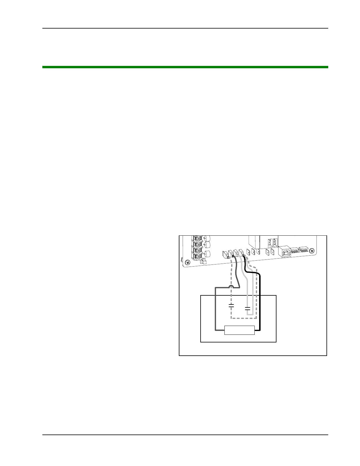
Take the following steps to mount a commercial
style 24VDC radio receiver (external antenna
type):
1. Install the receiver in the channel of the
chassis on either side of the control box.
2. Knock out the closest hole in the bottom of
the control box and route the wires to the
area marked RADIO OPTIONS. Only
three wire connections are needed because
the common wire and one radio output wire
are connected together. Figure 6-1 shows
additional wires from a two channel receiver.
3. Make sure to observe polarity and crimp
together the black radio common wire and
one of the radio output wires using a ¼-inch
spade connector.
4. Fasten the two crimped wires to the COM
terminal.
5. Connect the red wire to the +24V spade and connect the other radio output contact wire to the spade
marked OPEN.
Note:This terminal is the same as the input terminal labeled RADIO OPEN along the left edge of the Smart
DC Controller.
C
OM
EDGE
EYE
COM
+ 24 V
EMERG
OPEN
SHOW
LEDs
RA
D
I
O
OPTI
O
NS
E
D
G
E
+
24
V
O
P
E
N
C
O
M
D
U
A
L GA
T
E
B
A
U
S
E
R
2
C
OM
N
O
D
C
Two Channel Radio Receiver
Power
Shows connecons
for Remote Open
and Gate Edge (dashed line).
R2
R1