www.hysecurity.com Power D0536 Rev. C 2-3
Wiring 115VAC Power
For standard 115VAC power connection:
Verify AC power supply wires and low voltage (12V & 24V accessory
power wires) run through two separate conduits. The higher voltage
from the AC power supply may cause interference and anomalies in
StrongArmPark DC operation if the high and low voltage wires are
routed through the same conduit.
Maximum gate operator current draw is 3 Amps on a dedicated
115VAC circuit (20A dedicated circuit is recommended).
Make sure proper wiring is being used. The following table shows the
maximum allowable wire run from the power source to the operator for
various wire sizes.
StrongArmPark DC 115VAC: Wire Gauge versus Run
AC Power 14 Gauge Wire 12 Gauge Wire 10 Gauge Wire
One operator 115V 730 ft (223 m) 1200 ft (366 m) 1900 ft (579 m)
Two operators 115V 460 ft (140 m) 750 ft (228 m) 1160 ft (354 m)
NOTE: Table 2-1 assumes a dedicated circuit with an accessory power load up to 2A.
Additional loads require that the wire size be increased or the distance of the run be decreased.
To connect to 115VAC power, take the following steps:
1. Make sure the AC power is turned off at its source and the DC and AC power switches on the operator
are in the off position.
2. Access the input power wires and service outlet wires by removing the two Phillips-head screws that se-
cure the high voltage junction box cover.
3. The service outlet wires are solid copper and are labeled and bound together to keep them separate
from the AC power switch wires.
4. Wire nut or crimp bond the power supply wires to the black and white lead wires coming from the AC
power switch (no label).
5. Wire nut or crimp bond the equipment ground wire to the green ground wire in the junction box.
6. To activate the 115VAC service outlet, include the black and white outlet lead wires and the green ground
wire in the connections made above.
7. Neatly organize all wire connections and replace the high voltage junction box cover. Secure it with the
two Phillips-head screws.
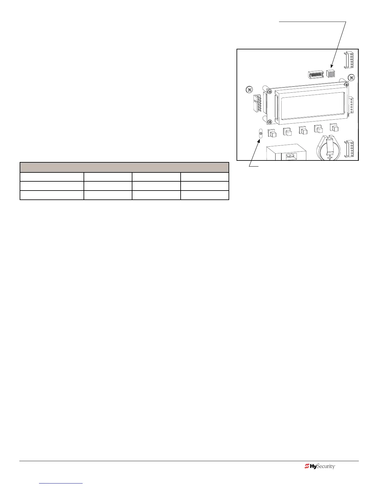
LED indicator changes color:
GREEN indicates AC power and RUN mode.
YELLOW designates MENU mode.
RED indicates Alert, Fault, or Error.
INSIDE LOOP OUTSIDE LOOP
USER RELAY 1
Electro-mechanical
RED ashing LED indicates software
and power is operational. Pulsating LED
slows when only DC power supplied.
 Loading...