–
5. Circuit Description
5.1 Front Panel
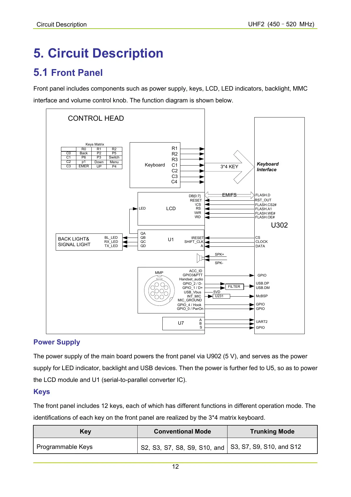
Front panel includes components such as power supply, keys, LCD, LED indicators, backlight, MMC
interface and volume control knob. The function diagram is shown below.
CONTROL HEAD
BACK LIGHT&
SIGNAL LIGHT
BL_LED
RX_LED
TX_LED
U1
\RESET
SHIFT_CLK
A
QA
QB
QC
QD
Keyboard
R1
R2
R3
C1
C2
C3
LCD
DB[0:7]
RESET
\CS
\WR
\RD
LED
GPIO_1 / D+
ACC_ID
Handset_audio
MIC_GROUND
GPIO3&PTT
GPIO_2 / D-
USB_Vbus
INT_MIC
GPIO_4 / Hook
GPIO_0 / PwrOn
MMP
U7
U302
3*4 KEY
Keyboard
Interface
EMIFS
FLASH.CS2#
RST_OUT
CS
CLOCK
DATA
U231
5VD
SPK+
SPK-
GPIO
GPIO
GPIO
McBSP
FILTER
USB.DP
USB.DM
FLASH.D
p1
P5
C2
P4
Switch
P3
Menu
C1
Back P2
Down
C0
R2
R1R0
Keys Matrix
FLASH.A1
FLASH.WE#
FLASH.OE#
RS
A
B
S
UART2
GPIO
EMER
P6
C3
C4
UP
Power Supply
The power supply of the main board powers the front panel via U902 (5 V), and serves as the power
supply for LED indicator, backlight and USB devices. Then the power is further fed to U5, so as to power
the LCD module and U1 (serial-to-parallel converter IC).
Keys
The front panel includes 12 keys, each of which has different functions in different operation mode. The
identifications of each key on the front panel are realized by the 3*4 matrix keyboard.
Key Conventional Mode Trunking Mode
Programmable Keys
S2, S3, S7, S8, S9, S10, and
S3, S7, S9, S10, and S12

 Loading...


