–
D804. It is used to detect both forward and reverse power of the transmitter. The forward power is
coupled to the diode D803, and the voltage is applied to the power control circuit (U801). Then U801
outputs the voltage VGG for controlling the gate voltage of Q805 and Q804, ensuring a constant power
output. The reverse power is coupled to D804. The voltage is applied to U802 and then fed into U302 for
detection.
Power Control
The TX power is controlled by power control chips U801. The forward power is applied to the directional
coupler, to output a voltage that can represent the forward power. The voltage together with the preset
voltage feeds to U801 to output a voltage VGG, which can control both gate voltage and gain of Q804
and Q805, ensuring a constant power output.
Thermal and Over-voltage Protection
The circuit comprises thermistor RT804 and resistor R884. The output voltage is proportional to the
detected temperature. Both the voltage used for temperature detection and the threshold voltage are fed
to the operational amplifier U804, to output a voltage signal that is proportional to the detected
temperature. The voltage is applied to software judgment via the diode D129, and then the preset
voltage will be subsequently changed to lower TX power, and to protect the PA from over-heating.
Pressure Pad Switch
The power control circuit includes a pressure pad switch SW1, which is controlled by the conductive
rubber part mounted on the upper cover. When the switch is turned off, the power control voltage VGG
will become low, and no power will be output from PA. Otherwise, PA will work normally.
5.3.2 Receiver Circuit
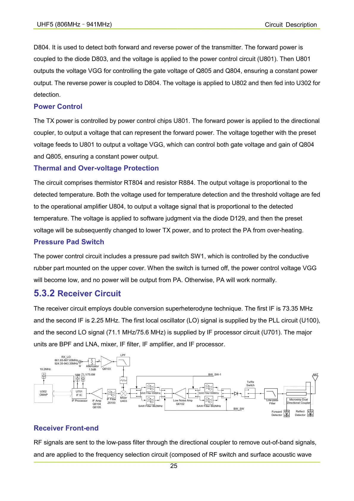
The receiver circuit employs double conversion superheterodyne technique. The first IF is 73.35 MHz
and the second IF is 2.25 MHz. The first local oscillator (LO) signal is supplied by the PLL circuit (U100),
and the second LO signal (71.1 MHz/75.6 MHz) is supplied by IF processor circuit (U701). The major
units are BPF and LNA, mixer, IF filter, IF amplifier, and IF processor.
Tx/Rx
Switch
Low-pass
Filter
Microstrip Dual
Directional Coupler
ANT
Forward
Detector
Reflect
Detector
SAW Filter 938MHz
SAW Filter 862MHz
Low Noise Amp
Q6102
SAW Filter 938MHz
SAW Filter 862MHz
Mixer
U403
LPF
1 2
Attenuator
1.5dB
1 2
Q6103
IF Filter
Z6100
IF Amp
Q6104
Q6105
U701
IF IC
IF Processor
U302
OMAP
19.2MHz
18M
71.1/75.6M
RX_LO:
861.65-867.65MHz
924.35-943.35MHz
BW_SW
BW_SW-1
Receiver Front-end
RF signals are sent to the low-pass filter through the directional coupler to remove out-of-band signals,
and are applied to the frequency selection circuit (composed of RF switch and surface acoustic wave

 Loading...


