Troubleshooting Flow Chart
–
[5] R368 and R370 have no soldering defects.
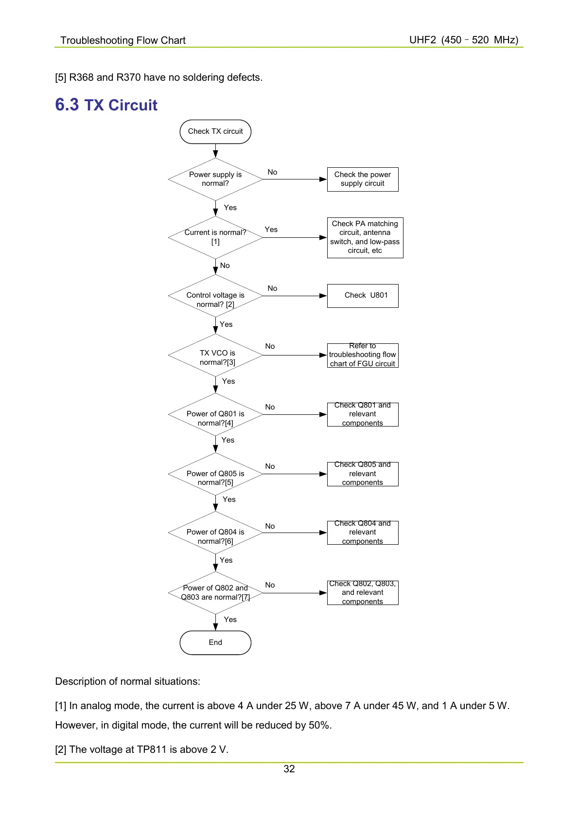
6.3 TX Circuit
Check TX circuit
Power supply is
normal?
Check the power
supply circuit
No
Current is normal?
[1]
Yes
Check PA matching
circuit, antenna
switch, and low-pass
circuit, etc
Yes
Control voltage is
normal? [2]
Check U801
No
No
TX VCO is
normal?[3]
Yes
Refer to
troubleshooting flow
chart of FGU circuit
No
Power of Q801 is
normal?[4]
Yes
Check Q801 and
relevant
components
No
Power of Q805 is
normal?[5]
Check Q805 and
relevant
components
Yes
No
Power of Q804 is
normal?[6]
Check Q804 and
relevant
components
No
Power of Q802 and
Q803 are normal?[7]
Check Q802, Q803,
and relevant
components
End
No
Yes
Yes
Yes
Description of normal situations:
[1] In analog mode, the current is above 4 A under 25 W, above 7 A under 45 W, and 1 A under 5 W.
However, in digital mode, the current will be reduced by 50%.
[2] The voltage at TP811 is above 2 V.

 Loading...


