–
7. Interface Definition
7.1 10-PIN Connector
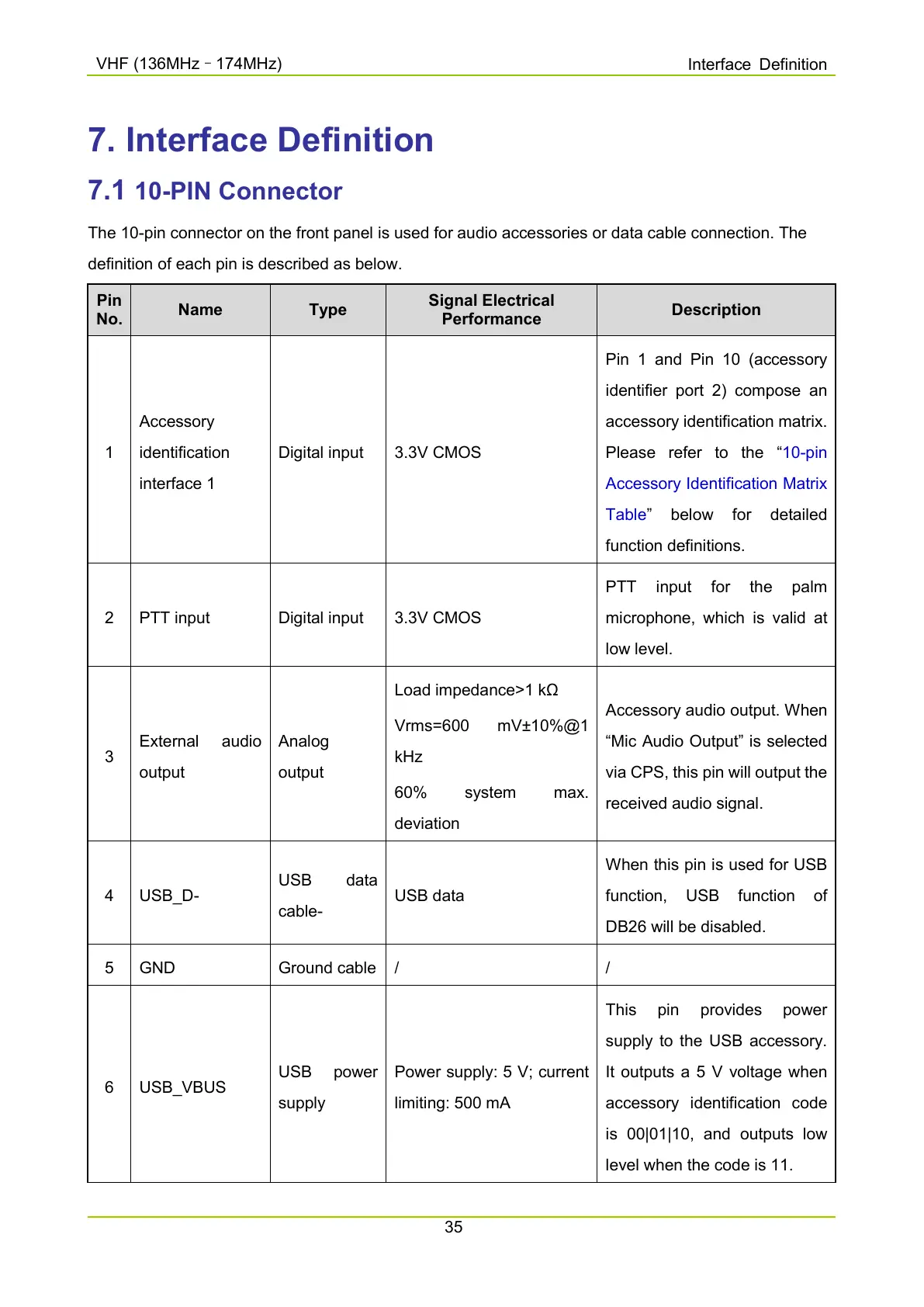
The 10-pin connector on the front panel is used for audio accessories or data cable connection. The
definition of each pin is described as below.
Pin
No.
Name Type
Signal Electrical
Performance
Description
1
Accessory
identification
interface 1
Digital input 3.3V CMOS
Pin 1 and Pin 10 (accessory
identifier port 2) compose an
accessory identification matrix.
Please refer to the “
10-pin
Accessory Identification Matrix
Table
function definitions.
2 PTT input Digital input 3.3V CMOS
PTT input for the palm
microphone, which is valid at
low level.
3
output
Analog
output
Load impedance>1 kΩ
Vrms=600 mV±10%@1
kHz
deviation
Accessory audio output. When
“Mic Audio Output” is selected
via CPS, this pin will output the
received audio signal.
4 USB_D-
cable-
USB data
When this pin is used for USB
function, USB functi
DB26 will be disabled.
5 GND Ground cable / /
6 USB_VBUS
supply
Power supply: 5 V; current
limiting: 500 mA
supply to the USB accessory.
It outputs a 5 V voltage when
accessory identification code
is 00|01|10, and
level when the code is 11.

 Loading...


