–
Troubleshooting Flow Chart
[4] The output voltage of U905 and U909 is 5 V and 3.3 V respectively.
[5] The output voltage of U902 is 5 V.
[6] The output voltage of U900 and U901 is 3.3 V.
[7] The output voltage of U903 is 1.8 V.
[8] The output voltage of U919 is 1.6 V.
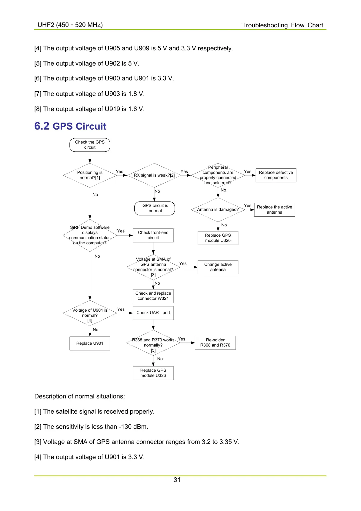
6.2 GPS Circuit
Check the GPS
circuit
Positioning is
normal?[1]
RX signal is weak?[2]
Yes
No
Peripheral
components are
properly connected
and soldered?
Replace defective
components
Yes Yes
Antenna is damaged?
No
GPS circuit is
normal
Replace GPS
module U326
Yes
Replace the active
antenna
No
SiRF Demo software
displays
communication status
on the computer?
Voltage at SMA of
GPS antenna
connector is normal?
[3]
Yes
Yes
Change active
antenna
Check and replace
connector W321
No
No
Voltage of U901 is
normal?
[4]
No
Check UART port
Yes
Replace U901
Check front-end
circuit
R368 and R370 works
normally?
[5]
Re-solder
R368 and R370
Replace GPS
module U326
Yes
No
No
Description of normal situations:
[1] The satellite signal is received properly.
[2] The sensitivity is less than -130 dBm.
[3] Voltage at SMA of GPS antenna connector ranges from 3.2 to 3.35 V.
[4] The output voltage of U901 is 3.3 V.

 Loading...


