–
Pin 1 Pin 10 Radio Status
desktop microphone with earpiece).
High level High level
The mobile radio is in USB slave mode, or it is not connected to any
accessory, or it is connected to a palm microphone without keypad.
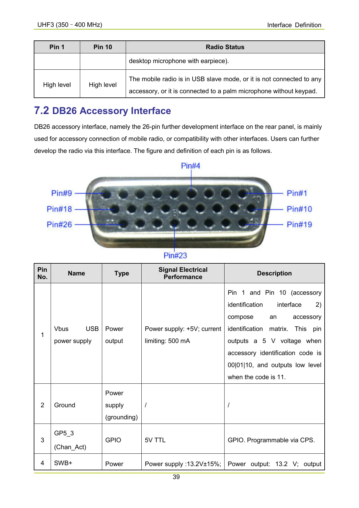
7.2 DB26 Accessory Interface
DB26 accessory interface, namely the 26-pin further development interface on the rear panel, is mainly
used for accessory connection of mobile radio, or compatibility with other interfaces. Users can further
develop the radio via this interface. The figure and definition of each pin is as follows.
Pin
No.
Name Type
Signal Electrical
Performance
Description
1
Vbus USB
power supply
Power
output
Power supply: +5V; current
limiting: 500 mA
Pin 1 and Pin 10 (accessory
identification interface 2)
compose an accessory
identificatio
n matrix. This pin
outputs a 5 V voltage when
accessory identification code is
00|01|10, and outputs low level
when the code is 11.
2 Ground
Power
supply
(grounding)
/ /
3
GP5_3
(Chan_Act)
GPIO 5V TTL GPIO. Programmable via CPS.
4 SWB+
Power Power supply :13.2V±15%;
Power output: 13.2 V; output

 Loading...


