Troubleshooting Flow Chart
–
circuit is disconnected during test.
[4] The gain is 16 dB and the input signal is 0 dBm at Q801.
[5] The gain is 16 dB and the input signal is 0 dBm at Q805.
[6] The gain is 13 dB and the input signal is 0 dBm at Q804.
[7] The gain is 10 dB and the input signal is 0 dBm at Q802 and Q803.
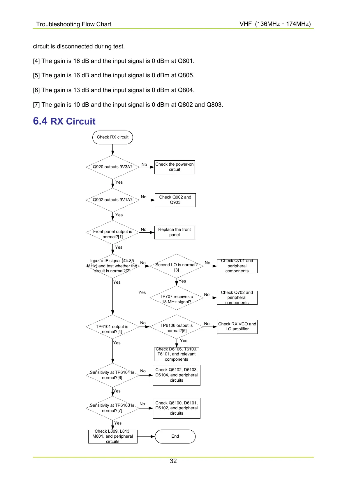
6.4 RX Circuit
Check RX circuit
Q920 outputs 9V3A?
Check the power-on
circuit
No
Q902 outputs 9V1A?
Yes
Check Q902 and
Q903
No
Front panel output is
normal?[1]
Yes
Replace the front
panel
No
Input a IF signal (44.85
MHz) and test whether the
circuit is normal?[2]
Yes
Second LO is normal?
[3]
No
Check Q701 and
peripheral
components
No
TP707 receives a
18 MHz signal?
Check Q702 and
peripheral
components
Yes
No
TP6101 output is
normal?[4]
Yes
TP6106 output is
normal?[5]
Yes
No
Check RX VCO and
LO amplifier
No
Check D6106, T6100,
T6101, and relevant
components
Sensitivity at TP6104 is
normal?[6]
Yes
Yes
Check Q6102, D6103,
D6104, and peripheral
circuits
Check L809, L813,
M801, and peripheral
circuits
Yes
No
End
Sensitivity at TP6103 is
normal?[7]
Check Q6100, D6101,
D6102, and peripheral
circuits
No
Yes

 Loading...


