–
VDD
SENCE
REST
CT
GND
C941
0.15u
4
3
X
C937
1000p
U910
6
3V3D
5
2
1 2
1
R932
4.7K
/PRST1
》
/PRST
D
913
MBRM120LT1G
MR
MR
VCC
GND
PFI
PFO
WDI
/RST
WDO
U906
1
8
7
2 1
MBRM120LT1G
《
RST_CTRL
R983 0
6
5
X
RESETIC
2
R920
0
3V3D
R923 0
C978
0.1u
3
4
X
D912
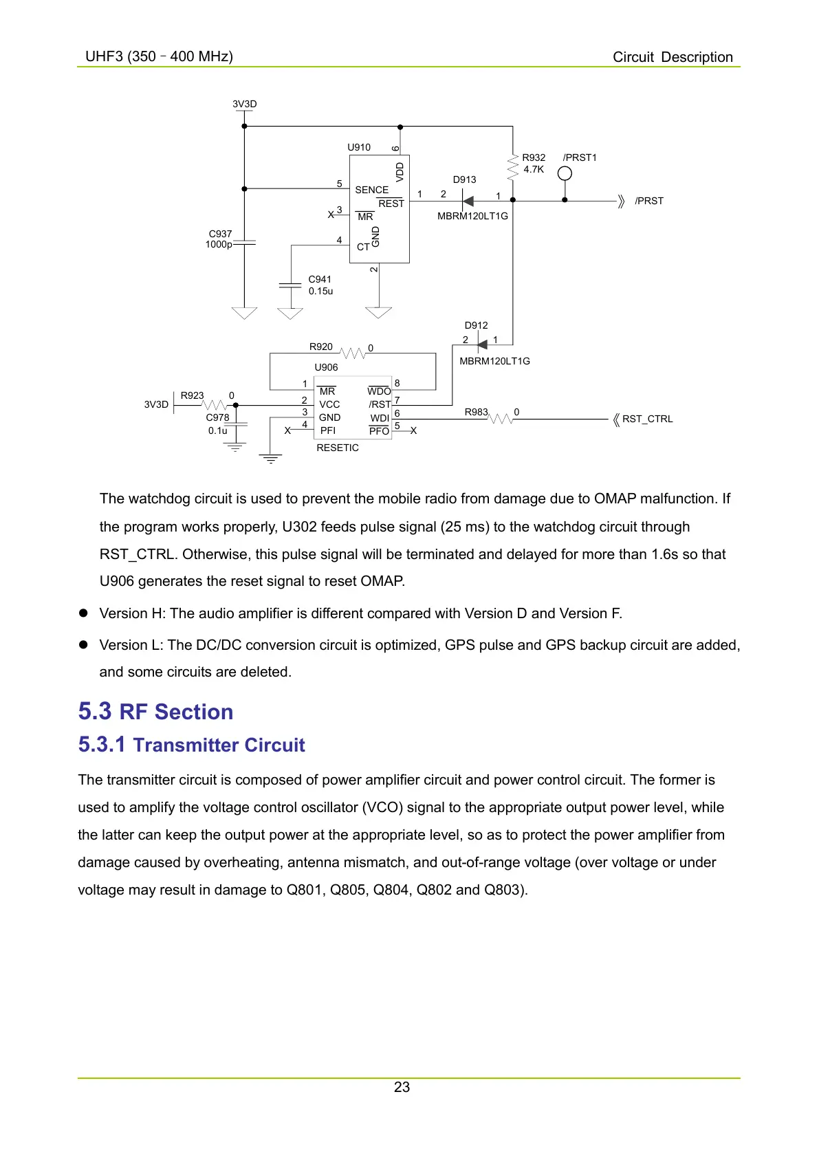
The watchdog circuit is used to prevent the mobile radio from damage due to OMAP malfunction. If
the program works properly, U302 feeds pulse signal (25 ms) to the watchdog circuit through
RST_CTRL. Otherwise, this pulse signal will be terminated and delayed for more than 1.6s so that
U906 generates the reset signal to reset OMAP.
Version H: The audio amplifier is different compared with Version D and Version F.
Version L: The DC/DC conversion circuit is optimized, GPS pulse and GPS backup circuit are added,
and some circuits are deleted.
5.3 RF Section
5.3.1
Transmitter Circuit
The transmitter circuit is composed of power amplifier circuit and power control circuit. The former is
used to amplify the voltage control oscillator (VCO) signal to the appropriate output power level, while
the latter can keep the output power at the appropriate level, so as to protect the power amplifier from
damage caused by overheating, antenna mismatch, and out-of-range voltage (over voltage or under
voltage may result in damage to Q801, Q805, Q804, Q802 and Q803).

 Loading...


