–
Power Amplifier Circuit
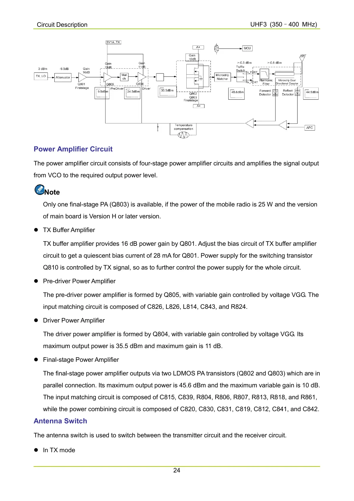
The power amplifier circuit consists of four-stage power amplifier circuits and amplifies the signal output
from VCO to the required output power level.
Note
Only one final-stage PA (Q803) is available, if the power of the mobile radio is 25 W and the version
of main board is Version H or later version.
TX Buffer Amplifier
TX buffer amplifier provides 16 dB power gain by Q801. Adjust the bias circuit of TX buffer amplifier
circuit to get a quiescent bias current of 28 mA for Q801. Power supply for the switching transistor
Q810 is controlled by TX signal, so as to further control the power supply for the whole circuit.
Pre-driver Power Amplifier
The pre-driver power amplifier is formed by Q805, with variable gain controlled by voltage VGG. The
input matching circuit is composed of C826, L826, L814, C843, and R824.
Driver Power Amplifier
The driver power amplifier is formed by Q804, with variable gain controlled by voltage VGG. Its
maximum output power is 35.5 dBm and maximum gain is 11 dB.
Final-stage Power Amplifier
The final-stage power amplifier outputs via two LDMOS PA transistors (Q802 and Q803) which are in
parallel connection. Its maximum output power is 45.6 dBm and the maximum variable gain is 10 dB.
The input matching circuit is composed of C815, C839, R804, R806, R807, R813, R818, and R861,
while the power combining circuit is composed of C820, C830, C831, C819, C812, C841, and C842.
Antenna Switch
The antenna switch is used to switch between the transmitter circuit and the receiver circuit.
In TX mode

 Loading...


