–
of the VCO. Q102 and Q107 constitute the buffer amplifiers for the transmitter circuit, while Q111 and
Q109 for the receiver circuit. The digital-to-analog converter (U500) modulates the TX oscillator signal.
5.4 GPS Circuit Section
GPS
module
U302
UART
GPS
Antenna
LCD
Power
REB-1315LPx
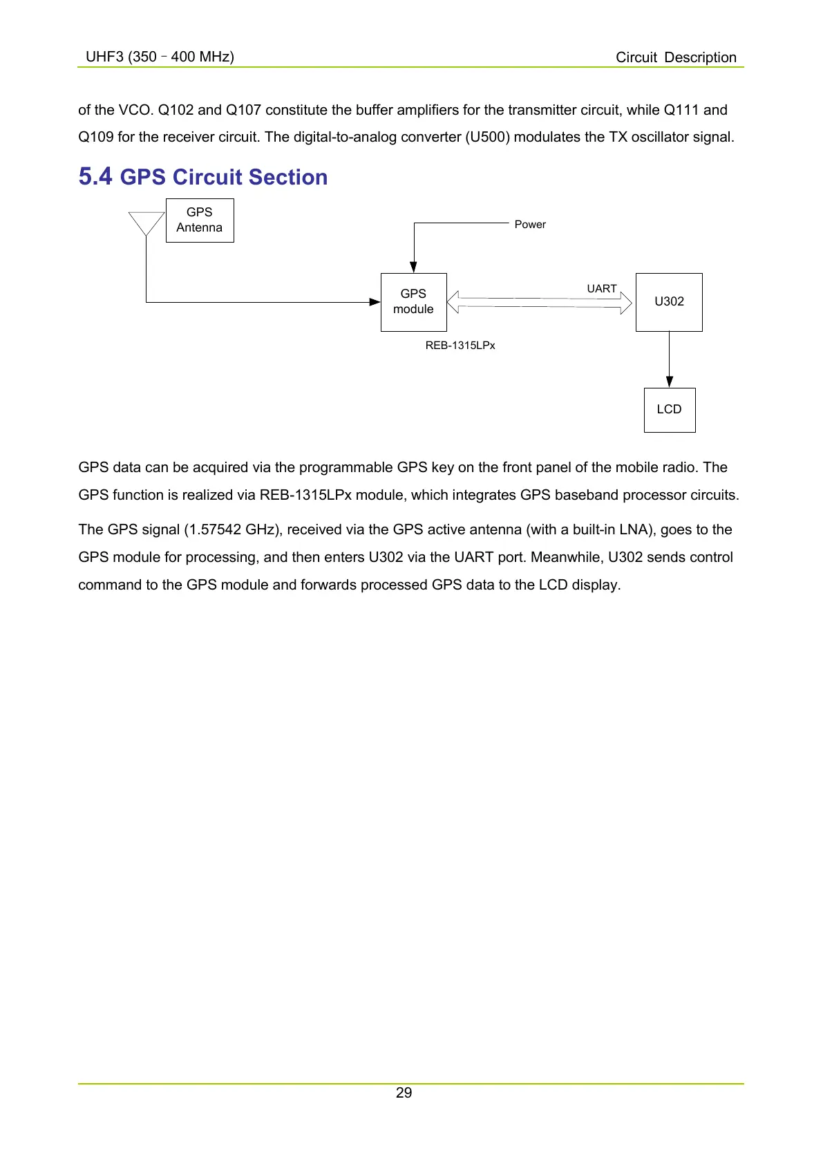
GPS data can be acquired via the programmable GPS key on the front panel of the mobile radio. The
GPS function is realized via REB-1315LPx module, which integrates GPS baseband processor circuits.
The GPS signal (1.57542 GHz), received via the GPS active antenna (with a built-in LNA), goes to the
GPS module for processing, and then enters U302 via the UART port. Meanwhile, U302 sends control
command to the GPS module and forwards processed GPS data to the LCD display.

 Loading...


