Troubleshooting Flow Chart
–
[2] The voltage at TP811 is above 2 V.
[3] The output amplitude of the TX LO signal at TP803 is about 10 dBm. Make sure that the back-end
circuit is disconnected during test.
[4] The gain is 16 dB and the input signal is 0 dBm at Q111.
[5] The gain is 15 dB and the input signal is 0 dBm at Q805.
[6] The gain is 11 dB and the input signal is 0 dBm at Q804.
[7] The gain is 10 dB and the input signal is 0 dBm at Q802 and Q803.
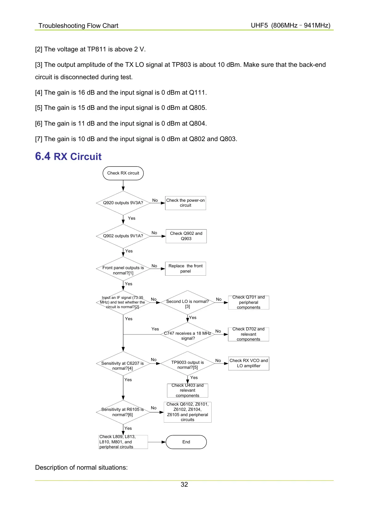
6.4 RX Circuit
Check RX circuit
Q920 outputs 9V3A?
Check the power-on
circuit
No
Q902 outputs 9V1A?
Yes
Check Q902 and
Q903
No
Front panel outputs is
normal?[1]
Yes
Replace the front
panel
No
Input an IF signal (73.35
MHz) and test whether the
circuit is normal?[2]
Yes
Second LO is normal?
[3]
No
Check Q701 and
peripheral
components
No
C747 receives a 18 MHz
signal?
Check D702 and
relevant
components
Yes
No
Sensitivity at C6207 is
normal?[4]
Yes
TP9003 output is
normal?[5]
Yes
No
Check RX VCO and
LO amplifier
No
Check U403 and
relevant
components
Sensitivity at R6105 is
normal?[6]
Yes
Yes
Check Q6102, Z6101,
Z6102, Z6104,
Z6105 and peripheral
circuits
Check L809, L813,
L810, M801, and
peripheral circuits
Yes
No
End
Description of normal situations:

 Loading...


