–
Pin
No.
Name Type
Signal Electrical
Performance
Description
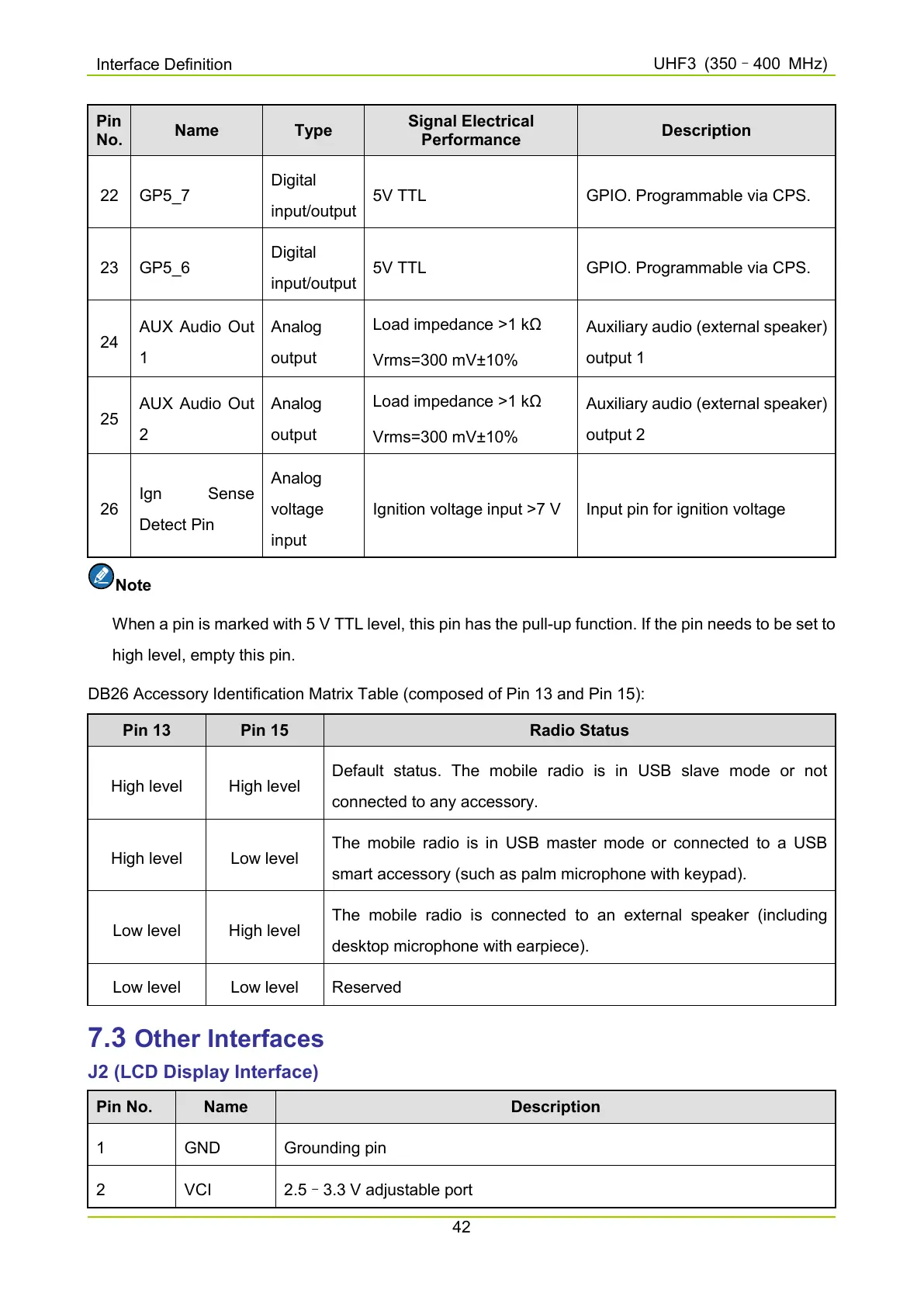
22 GP5_7
Digital
input/output
5V TTL GPIO. Programmable via CPS.
23 GP5_6
Digital
input/output
5V TTL GPIO. Programmable via CPS.
24
AUX Audio Out
1
Analog
output
Load impedance >1 kΩ
Vrms=300 mV±10%
Auxiliary audio (external speaker)
output 1
25
AUX Audio Out
2
Analog
output
Load impedance >1 kΩ
Vrms=300 mV±10%
Auxiliary audio (external speaker)
output 2
26
Ign Sense
Detect Pin
Analog
voltage
input
Ignition voltage input >7 V Input pin for ignition voltage
Note
When a pin is marked with 5 V TTL level, this pin has the pull-up function. If the pin needs to be set to
high level, empty this pin.
DB26 Accessory Identification Matrix Table (composed of Pin 13 and Pin 15):
Pin 13 Pin 15 Radio Status
High level High level
Default status. The mobile
radio is in USB slave mode or not
connected to any accessory.
High level Low level
The mobile radio is in USB master mode or connected to a USB
smart accessory (such as palm microphone with keypad).
Low level High level
The mobile radio is connected to
an external speaker (including
desktop microphone with earpiece).
Low level Low level Reserved
7.3 Other Interfaces
J2 (LCD Display Interface)
Pin No. Name Description
1 GND Grounding pin
2 VCI 2.5–3.3 V adjustable port

 Loading...


